Philips 213 u service manual

This is the 2 pages manual for philips 213 u service manual.
Read or download the pdf for free. If you want to contribute, please mail your pdfs to info@audioservicemanuals.com.

Page: 1 / 2
left right
philips 213 u service manual

Extracted text from philips 213 u service manual (Ocr-read)


Page 1

VI

NUMBER [56

PHILIPS

THE WIRELESS TRADER

2|3U

3-VALVE A.C./D.C. RECEIVER

VARIABLE-MU pcntode H.1-.
Aalnplifier, a pentode detector and a

pentode output valve are employed
in the Philips zl3U 3r\'alve (plus rectifier)
A.C./D.C. receiver. It is suitable (or
mains oi zoo-250 \' (4o-loo cps. in the
case of :\.C.).

CIRCUIT DESCRIPTION

Alternative aerial input connections
A1 and A2 (with series resistance Bl)
via series condenser 01 and Droitwicli
rejector L1, 022 (short-circuited on
MW. and normal LW. by switch 81) to
coupling coils L2, L3. Singlevtuned
circuit L4, L5, 025 precedes variablernu
pentode HF. amplifier (V1, Mnflard
metalliaed W130) operating with gain
control by variable potentiometer 38
which varies GB, applied.

Tuned-secondary transIormer coupling
by L6, L7. L8. L9 and 028 to H,F.
pentode detector (V2, Mulllrd metallised
130) which operates an grid leak system
with 010 and 310, Ell. ND reaction
H17. lay-passing in anode circuit by
condenser 014.

DC. potential develo (1 across Bll
section of V2 gn'd leak is ed back through
decoupling circuit m, 07 as 6.8. to
HF. amplifier, giving a simple (om: of
automatic volume control.

Resistance-capacity coupling by 314.
013. and 3.15 between V2 and output
pentodc (V3. Mallard P011360). HY

filtering in (2.0. circuit by 310, 016,
3.17. 010 and R18. Tone correction by
anode circuit.

fixed condenser 017 in

Provision for connection of bigh-im
pedance external speaker across specia
secondary winding on internal speaker
transformer T1.

When the receiver is used with A.C.
mains. HI. current is supplied by hall-
wav rectifying valve (V4, Philip! CYIC),
which, with DC supplies, behaves as a
low resistance. Smoothing by iron-
cored choke L11 and electrolytic con<
densers 019. 020.

Valve heaters are connected in series
together with scale lamps and automatic
current regulating barretter (Philipl Cl
or 010) across mains input circuit.

COMPONENTS AND VALUES

Values

RESISTAM L5 (ohms)
Ki J\A'n>|l ,. riPs ltSISLlIlII :uu.l)oo
It: .-\ena rniih shunt 100,000
R3 .resisllntr i,iso,wo
R. . ll 1'. {end none
Rs d on. Nsi>lfltllu ino
Rb . . , .liiicilcmiipling oo,ooo
R7 rm gain coninii t'irtuil unooo
R8 \r gain Control l2,5oo
R9 vi nnode derouplillg 1,000
kin ) . . . w i.: 0.000
l HI. iced . . 800,000
. .ncl anode decoupling 20.000
load , , . . 320,000
lm i . .resistanrc 500,000
IUD 50,000
klr i . .H F.in 50,000
1m 1 roan
Rig v; .n. misinnr. :no
R20 i ll.T.supplyb nsl inn

- Tun 04,000 0 n'SIsldrlI es in parallcl.

TRADER' SERVICE SHEETS

October 31, 1936

roxolzxsniis mun;
IFFI
c. Aerial series ennui-n, o-oor
c: Earth blaming (mliIenuI 0'!
C3 Aerial L.w. miioliiig iniiiiiiu o'oooos
C4 VI. cc, condenser o'nocnfi.)
C; \'i 5.0. b ~ pass i ovs
ca vi came 8 erpa<5 0'!
C7 Aiv.c. line decoupling | in.
ca . Gain conirnl l) ii 5
co ' ode deco uni
(:0 G. condo Cr
Cu \. 2 so. hyrpa i ..
cii v: annrle ninl so, decuunling
CH v: to vi L. r. plillg
Lu v: anode H .l Iss
83 }\'3 cc. .1" by passvs {
cu Tone Corrector
cm- \3 iiiiliode by-pnxs
5:3: } ILT. siiiooiliing i ,
C2! l mimic Iiy pit» .
c :2: mm.» tuning
C23: Aerial iiniiii LVI. lrlmmli
cu: Aerial rirciiii MM: trimmer
cm Aerial circuit tlllllng ., . 000045
cm; H.F. trans, MiWi lrinlmtr 1 ooooo.7
(:7: Hr. irins, liw. iiiiiinici 0 Moon
C25? H.F. trans, inning o-ooon
; hem
Approk
I min
(ohms)
Ll Diniiii-icli rr'jcrlol Coil, total . 4o 5
1: lAerinl coupling Coils J: 32:;
1-4 Aerial circuit tuning coils . 1°
Ls l 30 ii
L6 . . I iii-g
L7 } Hr. unnslmiiei pninnry I 1
t3 }H.F_ UMISILrliucl secondary 1 ,:_;
-/
Lia . Sipenker sperm coil W
Lu i l 1. smoothing choke 7mm
li Sprayer inpiii } 153";
trans. 00 U
SI»S.1 \anvbalirl ~wiirlrs ., .. k
Millris switches (gilngt'd Rx; . , - A


R9 N3

RIZ

CID


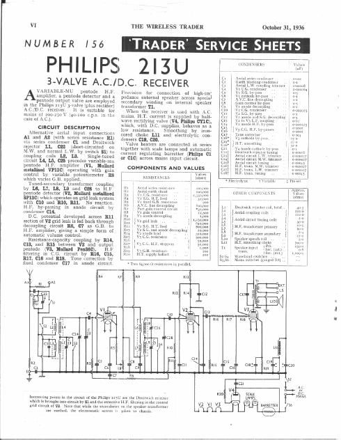
interesting points in the circuit of the Philips zuU nrc Ih: Droilwiih reiecior
which is brought into circuit by 31 and the extellsiwc H F. filtering in the control
grid circuit of V3, Nor: that while the secondaries on the speaker transformer

are unhed. the electrostatic screen l5

V2 VI

taken in chassisi

V3 autumn