Philips 210 service manual

This is the 6 pages manual for philips 210 service manual.
Read or download the pdf for free. If you want to contribute, please mail your pdfs to info@audioservicemanuals.com.

Page: 1 / 6
left right
philips 210 service manual

Extracted text from philips 210 service manual (Ocr-read)


Page 1

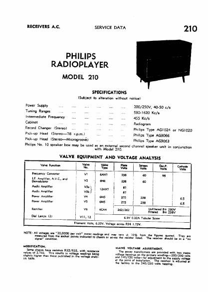
RECEIVERS LC.

PHILIPS

RADIOPLAYER

MODEL 210

SERVICE DATA

210

SPECIFICATIONS

(Subjeck to alteration without notice)

Power Supply

Tuning Ranges
Intermediate Frequency ...... ,. .....
Cabinet .. I 7 .....

Record Changer (Stereo)

Pick-up Head (Stereo~78 r.p.m.)

Pick-up Head lStereo-Mtcrogroové)

__... . ZOO/250V, 40-50 c/s

530-1620 Kc/s

455 Kc/s

Radiogram

Philips Type AGIOZI or NGIOZO
Philips Type AGBOGS

Philips Type AGSOGB

Philips No. IO speaker box may be used as an external second channel speaker unit in conjunction
with Model 210.

VALVE EQUIPMENT AND VOLTAGE ANALYSIS

i I V-lve VOIVC PM. Salon 0a.». om
V'l "3" l Nu. Volts Von. Volts Von:

,

fieqwncy Convener VI W7 1 238 l 60 l 95

u. Amplifier, A.V.C., and

Mammy v2 6N8 I 738 so i

Audio Amplifier van} ; I2AX7 37

Audio Amplifier v3b a7 l i

Pwer Amplifier 3 v4 6M5 i 275 j 23! : 6.5

Pawer mm" 1 vs 1 ms l 275 I 235 i 5.5

l

r a

Rectifier l v5 l GCM l 252 I262 Engaged a: £33

I
om Lamps (2; l VIIl 12 sav 0.3M Tubular Screw

Filament Vales, 6.35V. Voltage Across R34 l,73V,

NOTE: All vatupes are "20,0000 par volt" meter vending and may vny 1 10% (mm the figures unmade They .re

mensurrd from the locker point: Indlamd m chassis or

signal" condition

MODIFICATION.

Some chessls have "Elston RSI/R33, with misunoo
vlluls of 2.7m. This result: in voltage readings being
slightly higher than Ihose published In the volt-no lmly~
sis table.

news; the resislcr lined; The receiver Ihould be In a "no

MAINS VOLTAGE ADJUSTMENT.

The power transform: are pmvidld with two malm
voltage "goings on the primary winding-ZOU/ZSO volts
and 240/250 voles-1m Idiustment lo the supply vamp:
at the point of Inshllarion. The vecelver I: adjusted II
vhe fpctory tn the 240/250 volt hpplng,

Page 2

210

To IIMOVI CMIS "OM CHIN.

Withdraw th- power plug from th- maln! anti"
lock". Lucien m. fiv- Iulnb retaining grub mm; and
runw- knobs. Ramon cabinet back Banal. Unacmr
th- ndal and earth termlml Itvip and diaconuct th-
innlrnll atrial Itll.

Mum odd plug hum soclut on sub dianls. \Mth-
draw tha pickup. change aver pannl and mains pus-ply
plug: {rum thu'r waive Jul: on th- main dud;
Rel-cu mains Input lead from ratalnhg clamp at imr
left hand lib of ublnn. Unmw two 3/l6" mot-l
than! m hm duals aid- il-ng-s and withdraw
duals hum akin-L

Th; Mullen-ant of the chasm is a mural o! tha
above placed-n,

DIAL CALIBRATION.

.

In th- want of an arm-I ullbmicn Inn! wining nwr
Itw antln dial acalu band, cumin- an be affect-d
by :lmply sliding lhc cursor asuvany on the dial cord as
mired. A pulnur position unruly mmr th- Mala
stop muk (In) border ridtt hand slda cf pal-l dimld
«Respond with a tuning gang fully clmad utting.

ALIGNMENT.

Check dial alibratlm and if necasary adjust cumr
positiun as ducrlbed in tho iongoinc.

For l.F.T. and R.F. trlrmrm locations mm to :lram
diagram inm WIND.

Sat volume control in mxlmum, ton: and helmet
control to - antral pcairien, '

® cm LINE! 5" ®

:1.an vraw anon mm mm
mum wma m IN nasal: Basmoru


SERVICE DATA

LL Minn-ant.

Screw out iran more at 2nd LET. primary.

Apply modulated 455 Kc]: signal via a lOOpF tapa-
citnr to control grid lpin 2) 4% V1 and punk l.F.T
corn in the following autism:-

Somndary 2nd |.F.T.
Scmndary In I.FAT.
Prlmry In LET.
Pvlnury 2nd LET.
Do not up! any adjustments.

u. Any-mu.

Us: a Standard RMA. dummy aerial and apply ;
maria-tad R}. slgul to aerial terminal.

Alignmanr tram-c515 an: 1,420 Kc/s. ZXY (pa-k
oscillator (C10) and aerial lC4l trimril, and 60C
Kali. 71L lpeak L3, 4 oscillator slug whil- rocking
ganglt

Do not attlmpt to adjust the iron can of the aura
call.

SPEAKER CASING.

When speak" replacement is rue-nary. it ll nun-
tial to dctarmlnt aorrnct planing brim. connecting
new speaker: into circuit. Reference to the :lrcui'
diagram wlll flaw that one mics cull terminal of act
mullet is marked with a) sign, which is designalxd a
the punitive sldal

To daterrnlm tho positiva mminal, connect a barren
across the vein. call,- the positlve unm'nal will be can,
meted to the pasitiu side of th- battety when the can:
monument is out or forward. Speakers must be con-
rltcted a: in the drum dimmt