Philips 206 h service manual

This is the 4 pages manual for philips 206 h service manual.
Read or download the pdf for free. If you want to contribute, please mail your pdfs to info@audioservicemanuals.com.

Page: 1 / 4
left right
philips 206 h service manual

Extracted text from philips 206 h service manual (Ocr-read)


Page 1

llIIIlIIIIIIIIIllIlllIlIlillllllllIlllllllldlllIllllllllIIIllillllilllillllllllllllillllhldlllllhllllll l Ill llllllll ll:

TRADER "

" 603

SERVICE SHEET

l
l
Illlllllllilllllillillll'llI UUIIIllllllllllll'llillllllllllllllllllllllllllllll ll llll'llllullll II

EVERAL unusual features ('0 ion III
in the output valve circuit oi the
,_ Philips 206H. a 5»\'alvc (plus l'CCll-
fiei) Strand ACUDI? superliet operatiig
from mains of 203 250 Y, 40100( /S in the
case of AC The SW range is l6i7 50 ll].
Negative fccdrbatk'. hum ncuti alisaticn,
mains voltage adjustment and a magnetic
relay. in addition to the usual biiiiig
resistance. are all introduced in tlic
cathode circuit of the output "alve A
sw ch associated with the rela_ shotr
(sin nits the scale lamp until the V:ll\(s
have warmed up.
[ml/Inga date May, 1940.

PLATE AERIAL

IWIrr/rr: &

Supp/ante r m 711.-
ITlecrricul '

PHILIPS 206H

AC/DC

CIRCUIT DESCRIPTION
Aoi'lal input via mun isolating can,
dcus '5 c1, c1 and coupling win- L1
(SW) L1 (MW) mi L3 (Lu) to siiiglc»

tuIIeII win-mi. LII, cas (SW), L5, 036
(MW), La, (:36 (MY), whit-Ii ,imede a
tiiovlwheiuile tulvl (V1, Mullard metal-

lised EcHs) rilicinting m
Ihangcr With mumal (minding.

'I'III A and E \Ul'kPiS arc sliuntPII Ivy
Icsistanie m to maintain no continuity
IIr-IWFPII them. An II rejwtym' L7,
68 Ill V1 IltXlle control grid lead is
tunrd liy a \IlllrlIIIP Illlnrtlllbt) r'ore. ('onr
drnsei's ca and CD across IIIIP aerial (3min
ling,r colls tunc them to resonate somcr
where outside thcii ll31)CCll\0 operating;
hands.

The roof and base of the cabinet arc
Iincd With metallic scrunnig foil: that
In the rcol 1, (IJllfiEtlFll directly to A
socket, via a soldvr -g COHHLCUOH 89,
and may he used an emergency atrial;
that on the Ilflfil acts as a normal screen.
and is returned to chassis dirpctly via
a separate, mains isolating condenser 05.
A second soldcrrtag connection ea is con
ncctcd (iircdly to the earth socket.

v1 oscillator anode coils L11 (SW).
L12 ()IVV) and L13 (TRY) are tuned by
040. Parallel trimming by 016 ISVV],
638 (MWI and 039 (via S10) lL\V);serics

Imqupm ,

SUPERHET

I. 1,; by cm (_\i\\') find. car (I.\\').
ltcaction coupling: by grid coils L8 (SW).
L9 (M\V) and Llo (LW).

Second valve (V2, Mullard metallised
EFB) is a variable mu RF pentode open
utiiig as llflel'lm-(llllle frequency amplifier
with tuned-priiiizn-y. tuncd secondary iron
(lust clireil II'MIISIUIJHeI' couplings cm, L,
L15, C11 and 019, L16, L17, C20.

Intermediiterlrequenay no KG/S.

Diode second detector, fed from tap-
ping; mi L11, is part of double diode pen»
lode output valve (V3, Mullard GBL1).
Audio frequency component in rectified
output, is dcvclnptd across the manual
volume control R11, which also operates
as load resistance, and passed via AF
coupling condenser 025 and grid stopper
R14 10 CG of pI-Iitodc so tion. which pro,
\idca the total AF nmplificution. IF filr
towing liy 022, R11 and 026.

Svcond diode of V3, fed from tapping
on L16 viii 024, provides DC potential
which is developed across load resistance
R16 and fed back through decoupling
circuit as GB to FC and IF valves. giving
automatic volume control.

When the receiver is operating from
AC mains. HT current is supplied by IHC
haltwave rectifying valvo (VII, Phllips
0Y1), which, with DC mains, behaves
as a low resistance. Smoothing is effected

gr)

C10:

W?

RSI k9

Cl/=:

IV (15
u [5 r L9
. i1
Kl -T-;° #635 In R6 57
SI 51 51 I
C4
C5 Hog
L2 Lt: 7
xi lo:
9.2 l
..

£g,_c_m_iu££~

CM

l

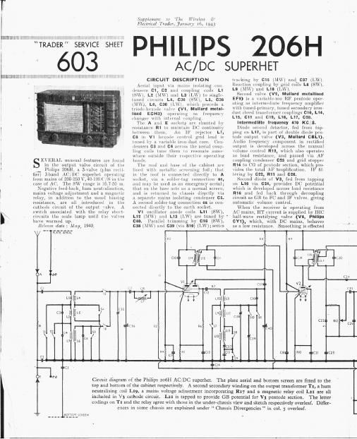
Circuit diagram of the Philips 206H ACIDC superhei. The plate aerial and bottom screen are fitted to the

top and bottom of the cabinet respectively. A second secondary winding on the output transformer T1, a bum

neutralising :oil L19, a mains voltage adjustment incorporating R17 and a magnetic relay coil L21 are all

included in 13 cathode circuit. L21 is tapped to provide GB potential for V3 pentode section.

codings on T1 and the relay agree with those in the underichassis view and sketch respectively overleaf. Dider-
cnccs in some chassis are explained under Chassis Divergencies in C01. 5 overleaf.

The letter

Page 2

Supplzmmt to The Wireless (9 603 PHILIPS

E39422! my, fury 16 use

206H

Plain view of the . " . 3 VOLTAGE
chassis, 030 is .. i i « ADJUSYMENT
indicated beneath > L7 CORE

t
1 Cal; it is partly Aommzm
1 obscured by the ,'
l gang uniti V2
5 holder and the mag»
netic relay are
almost completely
1 hidden by the IF
l transformers, but
i the relay is shown
1 in a sketch in col. 6
1 overleaf. Resist-
: ance R14 is
l mounted on the top
t cap of V3. The
respective connec-
tions of L19 and
L20 are indicated. -
R17 is attached to . l , REM?
voltage adiustment -' ' _' - LZl'SIZ
terminals 3 and 4,
and is shown here
3 dotted through the

1' ,
pane , , LEAD ro PLATE
l _________ 4 _ t» AERIAL CONTACT
liy iron-cured uhnke L20 :Iliil (lkkllUlytlt' » pull, of :i iiiiigneiicnlly operated relay. in; in< voltage) iiiid scale lfliiip ln'olei-tiun.
cuntleiist s 030, 031. zinil is {leHilltetl litter. A third isolating (H \.\])li\lll£(l below,
Valve heaters, together With current condenser 01! returns the metal speaker 'lh. nu put trmlsfmqnm- T1 has 9w

regulating hairetter (Philips 01) I'rzune to L'llll>Sl>. spimulary Wlnfllngn : one, [or ,wzile lamp, are cuiiiieuteil in series HL

Letneen the tan: identified in our
(hit input. uiicuitt Filter comprising OUTPUT VALVE 3 W, by the 16m: 0 and u- and um
:nr-Loruil chokes L22, L13 and condenser The uithode itiri oil of V3 ls compli- other 0 inrmitle the negative )fomeuck
caz Mippresm mainsrimme inter name, (sated by the in Hslon in it of arrange. g0 115,0 betwmlmgsd and e The 1mm.
while the heater and limrettm' ,mms tum; for negative teed-hack hum mu. k int-"him m the MIME Ohm Wm
mo bypassed by caa and can. sm is titiliszitiun, hm utljllstllivnt (according to m. Mark-Wk vintage h we infirm]
- iv! -1 v2


llie ll'l smoothing r: mke L10 also llils
mi llm' iOi" [it Second winding, L19. Hum
m lilgPS t ewluped ilk? s» L20 in tlie prn
ul smoothing result in image Voltigv»
' iiillcr amplitude appearing 1| .
'llll am for] in lulllrllllflsfl into
(ailiodc ("iClllb to neutri ,e llllllli

,\s Llieie is no voltage adjustment of
tln normzl type in the mains input civ-
iint. tln: lll line \oltzige will he llelflr
llllll'll liy the voltage of the mainsi mill


in UHltl to t,0[ll})(l]:al(! for thi it two
[)O:»itJUll grid bias adjustment is provided
[01 V3 in the form of {l lllflllli voltage
luluslmélll panel, comm-hing 1e fltflllcfi
V R11, Wlllrll is included in V3 lifllllnflt
flag uirznit. a FliOlL'ClTClllllllg link, and tom
llNK toriiiinuls arranged in ii vertical column.
For ]Ila,ll] of 200225 Y. the link is bo-
"9 119.. twnn terminals 3 and 4, where it short-
404 Tr: tir it R17; for miiinii of 2257250 V, it
is UMWCQL tCIInlnfllS 2 and 3, so the R11

m7

is loft in (ii-unit, and increases the GI;
voltage for V3 pentodc.

"lie l'ourtli device in the cathode Uh"
lllt is th- winding L21 of the magnetic
scale lamp protecting relay, This provides

Ni it;
n
aJ
t.n
I:
it

' r ' Wfififl the rush )nfe across which the grid bias

0| / \iiitiioe ix developed, and . takes the

9 L #02 plate of the normal sell'vhiasing eathode

KELAY V4» i'osistttnce it IS tapped to provide the

l h .fi coirwt potential. In the relaxed posi»

-.G2 r H-.' tini, when the set is switched off, the

J H rolx) switch 512 is closed and the scale

C3, k w '5 lump won, i'euited. \Vlieu v3 hnalliilll

:l : Linw to WIN up, however, after SWlLt'llr
MENU" my on, c: tliode current flowing through

Vl V3 V2 TH? L2} 84 L2! (ltklglsfs the magnet and opens the
M . \ ) Wr-/>-o«o--> w h-h, to that the smile lamp lights up