Philips 200 u service manual

This is the 2 pages manual for philips 200 u service manual.
Read or download the pdf for free. If you want to contribute, please mail your pdfs to info@audioservicemanuals.com.

Page: 1 / 2
left right
philips 200 u service manual

Extracted text from philips 200 u service manual (Ocr-read)


Page 1

[All right: reserved. This service data shed i~4 he copy-
right oi Winzuiss rt ELECTRICAL Tiumm and may not,
be reproduced, in Whole or in part, witrout permission]

TRADER SERVICE SHEET

1006

risllin'lili to operate rr-om rumouv At.
or mean V De. muius, the rnilip; 20w is
n 4-vulve (plus rectifier) threerimlid tshlu
onporiiot housed in a plastic cnhiuet. Tie wave-
band ranked urc 13.2mm, 135.1»6503m, 1,15-
2.000ui.
Renew unn- uni uvlgmulfm'l'r May '5! [12103.
pins inn-11M m.

CIRCUIT DESCRIPTION

Input [ram Belicantuineu plute neriul or
external sonnl. via. coupling coils, L2 (s.w.;,
L3 (MAM) w single-tuned circuits M, 1515
(s.\\.), L5, as (\I.W.). 0n I..w. sr tlosrs
und 5: opens, coupling the aerial input via the
l'UmmUH impedance of 02 to the Miami circuit
binned by L5. L3 and 025. 1.1". fllhring by
L1, 012. RI shunts the aerial input to prevzuir
modulution hum. 0n MNV. 52 closes, shunting
R2 M'lufis L8.

Find. valve (VI, Mallard UCHIZ) is a lode
licxude Vuhe operating as frequency changer.
Oscillator unmle coils L! (stun), Ls (M w.) ale
tuned by 029. L9 is also used for L.V\' wilt
it is shunned by (:26. Parallel trimming by c
ruw.) and 015, on (L.W.); series trsi: ' h3-
E21 1M,\N. Bull L.\V.). Inductive re
coupling iiy LG (S.\V.) and L7 (BLW. and L.\V.)
viiLrii :ulrlitinnnl coupling across the common
impedance M (221 m: M.W. and L.\\'.

Seamud Vulve (V2, Mullard UFM) is u
variable-mu ILFr pentode With tuueii trans
iurllier (-muiliugs as, L10. Lil, (is and all, L12,
L13, on.

Intermedlzle \nqumcy 410 lie/6.

Diode signal detector is part oi doulle diode
lriude vzilw, (VI, Mulllld mum). AF. com-
ponent ill rectifier: output is developed across
volume control R10, which act! as Hilde loflllr
and is paused via series capacitor 615 and grid
wtupper an to grill oi triode section. Second
(liode 01 V3 is conumtell to (hassle. H.135 ham-t
at the low level settings of the Volumtr conti'nl
IS provided by R9. 01.

D13. [idem/in] developed ncrosa Vuluml) control
RIO is fed back to EC. and LF. stinger an Mar
giving automatic gain control. LF. illtering
by (:13.

Resistunre-nupucibmce coupling between V3
mode and pentods onlput valve (in, Muilarn
uLll). Tone correction in anode irculi by on,
try the negative feed-hack volt ge developed

Supplame'nr to Wireless 6"
Electrical Trader, August 18, [951

PHILIPS 200

3-band A.C./D.C. Table

ulioss R15 in the cathode Circuit. Mill by feed-
hunk of speech coil vollugw alipeuiug across
T1 secondary to the grid circuit of V1 via (:11.

1LT. current is supplied hv I.H.C. rectifying
valve (V5, Mullam UVM). Smoothing by elec-
trlilytll' uiilml'llui'u 619, cm and rrsistor R21.
m. nltenng hy :21. mo protects vs, and
thermistor RI7 protects the scale lamp and
heater chain, flflilill\lu current surges.

Valve heaters. together with scale lamp,
thermistor, nullast resistors R18, H19 and volt-
age ndiustment resistor R20, are connected in
~eries across the mine input.

GENERAL NOTES

SWIltmeS.751-S10 are the Waveband SWiLuilel,
gungcd in a three-position rotary unit below
lhe ChrtSSiS. :5 position is indicated in our
iiiiiler-cliassiii View, :tnil shown in detail in the
diagram overeat, where it is til-awn us seen
{mm the rear 01 an nvertcd chunsin.

The tahle below it elves the switch positions
illi" Llie Lhree lollbrnl . hiring. starting from the
lullv :tntirclockvl'iSe poaibion ol the control. A
«lush Indicates open and c nlosod.

{'nnriiilmd ml. 1 7le)

COMPéNEfiTs AND VALUES

RESISTORS \nlucs Loca~
imam
R1 10m .62
R2 . . .
R3 Him ..
R4 Y1 use. CG.
R5 M.W. oso. shunt
lie Osc nnodeioed
in \l , v2 9 «iron
1L8 A.(LC. decoupling
lti: 'lone compensator
RIO Volume control

G.

ill 1 V3 C
\ C

R12 . stripper .

K115 Vin 910ml

K14

R15 .

{16 V.) surge 1i iiu'r

lll'i' Thermisml' .. - E21
15 Heater hullflsl{ 43W} (71
Ill 9 resistors 200 Q C 1
R2" Voltage alllud. 820 CI
K21 Lil. smoothing 1110 E2

027:
(:23:
(32M

}

}

Super/let


CAPACITORS i Values Locu-i

iomi
Ae 'al seriix 0 OOIuF -
i..w murphnp 0001mm G2
L.w. no a] trim . . 901:1? G3
Vi ho tau. iOUpF F2
151 1.1. trans. llUDF A1
tuning lilipF A1
V1 use, 0.6. . . rrph' F3
A. .C, decoupling 0 Ui'mk F3
Oscr node coup. 470pF GS
V1, V2 511 devour. 0 IMF F2
2nd LF, { llODF Bl
tum R .. IIODF 51
LF. by-pas SGDF E3
Tons campvmsam o 01 uF E2
A. l. coupling 0 3,03%}: gig
Neg. feed-back ZEDF E2
Tune com-rhu- 0 00mm ('1
. . 50oF U1
H.1.amoolhlng . {i . F C1
RrF. by-pass . (J 033! D2
filter tune PF -
. Vi aerial trim. 30p! F2
M. aerial trim. lZSpF Q3
AP tuning 5489])! l A1
, . 'mmer 5751717 F3
triu'ker 575pF 03
M, oso. trimmer :SUpF 03
Oscillaior tuning MBQDF A1

Electrolytic. T Variable. 3 PIO~BDC.

i " Swing " value, min to max.

aiaiaaerisi

I

557

FHC

Ml

mm-

(i;

in

C:
20

'vS
I

P-Mww.-...

x/S(Alelamu

i?) rm 1
mwflgwfliwmfim

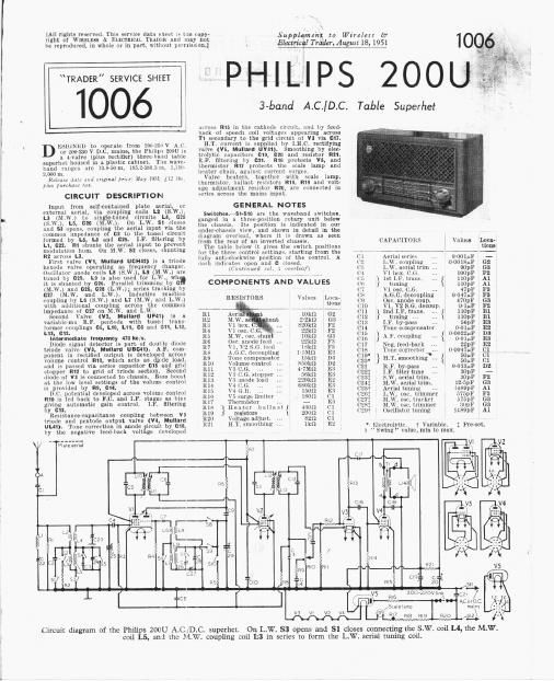
Circuit diagram of tin: Philips 200U AlC D.C. superhet. 0n LW. 53 opens and SI closes connecting the S.W. coilLA, the M.W.

200»230v lrnu
m6 1

coil L5, and ihc MAW. coupling coil [:3 in series to form the L.W. aerial tuning coil.

"LCPi /

Afar D.C.
mains

Page 2

l 00 PHILIPS
ZOOU
l 7 77 militant ii
OTHER (lOWYONFJNTS Values Lorry
(Ullmi) tlnll'l
l Li #1}. Iiltcr coil 304i (7
LZ ' l2
3 loin mu. l . 23g 35
L5 14 G2
L6 on (i5
{3; Oscillator rails. 51; :1
119 2'l G.
L10 1:: 11 12-3 Al
L11 trims i 12 X Al
L12 2nd I 1 12 u m
lrl3 tram 12"; Ill
Lu Spree]. coil 5-0
TI Primary . 380-0 (l
Secondary. . 0-3 83
31-510 Waveband switillcs 7
511,
82 Mains Sufi. g'll RIO - 2

Gui-n] Noun-continual

S", 512 are the mains switches mounted on
the volume control mo. _

nan lulu-This cunsiats of A alnp lil
metalliud paper gummed tn the moi of the
uhinet. _

Scull Luna-This is a Ill p5 type 3007 with
I tubular bulb Bnil an MILE, base. It is rated
It 20V, 0.1 A. _ >

M-im Voltage Animlmnl.7Thil consists u!
a single link, indicated in our under-chassis
view, which when sci. (or 200-220 v 4.0.01' mu
operation (figure 1 on plxulin strip in line with
window) PllOl'tS out KW. For 221.2an ALC. Dr
2211-230V D.C. operation (figure Z In Vllne_ with
Wlndow) the link it open and R20 IS in circuit

Tuning Conn-Only Iour coils are uied .lo
rover the three wuvebnnda in both l-he aerial
Ind oscillator circuits, these tolls being coil-
Ducted In the conventional Way Ior 8.. und
MW. coupling and tuning, and In the In human
manner {or LlW. operation. _ .

M.W cnupling coil LI is connected in series
with M.W. tuning coil L5 to form thlr L.W,
tuning coil, the aerial being coupled up the
common impedance of 62. In the oscillator
utnga, L.w. unvorugc is ontgiueq by using the
NLW. circuit and shunting It with 026.

nrivo cord unplulmom.-About lift «heard
in required. and it should be made up with a
loop {It Pncll I'llll tn measure 86.5 mm (34.06ln '(ll'
upinl overall. llalllfl spruiul metul collurs to
clamp the Grills. Turn the gang to maximum
capapitance. hook one end oi the cord to the
spring and run on as shown in the sketch
(col. 1), .Ktllrling alitlrulnckwise mllnrl tin drum.
[)0 not hunk the end 01 the spring to in anclmr
til: until Llll l'llll of Hit run. when hulll mull
luop: an ~|'('Ill[ll in it _

Modlficalions.7[n sump models It 1k) grid
lkvppcr is Connected lletween the Junclion llI
GIG. RM and VI control grid, and I 2711
resistor lh l'nnlwl'lrll lwlwecn SE arll till
junction of L5, L7.

Diagram of
the wave7
band sw.lch
unit, With the
associaled 1
table below. 1

Switches M. W. S.W. l. . W,

m
u.

c
E
0

Supplement [0 Wireleu Gr
Electrical Trader, August 18, 195i

D ' Vgli-Sl ;

Undersidc view of the chassis. C24, 026 and (327 are special Philips lrimmers.

VALVE ANALYSIS

Valve voltage: and currents given in the table
lielnw arr those taken frnm the munulactllrers
information. They were measured on a receiver
which was operating Irom A.C. mains or 220V
with the voltage adjustment net appropriately.
The volume control wits turned to muimum
but there was no signal input.

Voltage readings were measured with : KLEIN)
"gnu m-r inn mlm. i-lmisis lining negative.


l
Anode l a wen i mini.
Valves *7 7
mA nlA \'
. 1..., 2.1
H Um: Oscillator} 1-5 . 7
. in 3-0
V2 IT I ) 20 m
V? Uli . 7 7
Vi Ulill in] 9-0 8-5
V5 ("1'41 20% 7 meg-0


22 urnsrmmd
: own spindir\
\


3 turns round 7/
canimlsgmdle"

Sketch showing the tuning drive.

DISMANTLING THE SET

Removinx chassis-Remove two control knoll:
{recessed grub screws passing through
spindles);

ilnsolder plate aerzul [and irom in termination
on L2 (lucatinil relertnc: (12};

remove rwo cheésehead bolts with clumps
=Lcurinn tho roar (dg( or the chassis;

. Plan view of the

chassis. The tags .1 ®
on T1 are coded

. :25
and to agree wrth i
corresponding :29
points in the
circuit diagram. 9 Lil


l @obél

slacken oil the screw on the cursor curiae.
:wcvssilile through the liflSE oi the receiver.
and disengage the drive card;

withdraw chasxis to the extent 0! the speaker
loads, and ullwlder them from the speech coll
up.

When placing. connect the black lead to the
lower speech coil tag and the yellow lead to
the top tag.

CIRCUIT ALIGNMENT

All the following adjustments can be made
accessible upon the removal ol the Cabinet hack
and base cover (one unit),

I.F. stager.7Switch set to M.W.. tum gun!
to minimum and volume control to maximum.
Unscrew the cores of coilu L18, L12 (location
reference Bl) and L11, L10 (Al). Garment the
output of signal generator via a (Loan?
capacitor in the live" lead to control grid
(pin 6) 0! V2 and chassis. Feed in a modulated
470m; (638.3111) signal und adjust the cores
of LI! and LI! ior maximum output. Transfer
signal generate leads to control grid (pin 5)
of V1 anll Chas: '. Adjust the cores of L11 and
Lin for maxrmum output, reducing the input as
the circuits come into line to avoid A.G.C.
sflects. Do not readjust the cores of L13 and
L12.

LF, Filler.7Transter live gnal generator
lead to A socket, and with the set switched to
\[.W. and the gang at minimum, feed in a
.tlnliuv l7lllu' ~ ~lgllal :lilll iIIl_lII.~li 022 (in min
front oi cablnet) ior minimum output.

ILF. and oscillator slantiuheck that with
the gang at maximum the cursor is about
Imm to the left of the, M " at the end 01 the
M.W. tuning scale. 014, 625 and 017 are
trimmed hy adjusting the umount of Wire Wlth
which they are wound. Wire can be removed
but none must he udlled ll it is found that the
capacitance of one 0! these trimmers needs in-
creasing, a ' trimmer should bi: fitted.

S.W.-Switi'li set to 81W. and connect the
output or the signll generator "live" lean,
Via at suitable dummy aerial, to the A socket.
lived in a 13.76111 (21.8 M055) slxnal, tune it in,
umi adjust on (F2) inr minimum output.

M.w.7Switcll set to M.w., turn gang to
minimum capacitance and lead in a 184m
(1.630klt,3-) signal. Adjust 028 (GS) and 92
(G3) {or maximum output. No adjustment
should be required at the LF. end of the hand
and 07.7 (G3) should not need adjustment. It
is set. at Hookers.

LVI ~§witcl| set to la \l'. and tune to approxi-
mately 1.245m. Feed in a Lusm (2A1kc/s)
signal and adjust 026 (F3) 101- maximum output.

B C

SpnSk'e
lead


CILC l2

pruned 1'1 England by (nmunll Press Ltd, Pans Car/1M, Lari/inn, SE 1