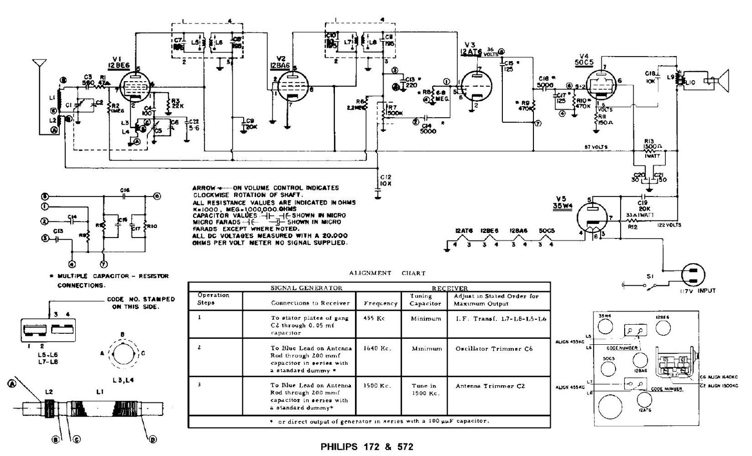
Philips 172 cd schematic

This is the 1 pages manual for philips 172 cd schematic.
Read or download the pdf for free. If you want to contribute, please mail your pdfs to info@audioservicemanuals.com.

Page: 1 / 1
left
philips 172 cd schematic

Extracted text from philips 172 cd schematic (Ocr-read)


Page 1

67 VOUS

06

CD

(9-1

|| (3

3)

l ULTiPLE CAPACITOR - RESISTOR
CONNECTIONS.

00M 0. STAIPED

ON TRIS $105.
3 4

l 2
L5.L6

L7- L8

Ll

'; il'i' I!- ll
.- ..«.q».m~'1'l

RROWEON VOLUME CONTROL INDICAYES

IITV I

cmcxmss ROTATION or SHAFT. I V5
ALL RESISTMCC VALUES ARE INDICATED IN OHHS 35W4
KIIOOO . NEG-IOO0,000.0KNS
cmcnon VALIJES-{i- 463nm u mono
mono rAaAos-{E- -{j- sum m mono
FARADS EXCEPT WHERE NOTED. mgr; [gage [23s 5005
ALL 00 VOLTAOES MEASURED WIYH A 20.000 /\ /\ /\ /\
OHMS F'ER VOLT METER N0 SiGNhL SUWUED. i 3 3 4 3 Q 5 4
ALIGNMENT CHART
. SIGNAL GENERATOR REQEIVER
Operation Tuning Adjust In Stated Order [or
Steps Connections to Receiver Frequency Capacitor Maxtmum Output
I I I I
1 To stator plates of gang 455 Kc Minimum 1.1. Tranof. L7-LB-L5-L6
CZ through 0, 05 mi
capaCItor L5
' ' ' I mouossu: _
2 To Blue Lead on Antenna 164D Kc. Mlnimum Oscillator Trimmer C6 L6
Rod through 200 mmf
capacitor in series with
a standard dummy
. I I I
3 To Blue. Lead on Antenna 1500 Kc. Tune in Antenna Trimmer C2 AUGN 455nm U-
Rod through 200 mmf 1500 Kc. L9-
capdcitor in aenea with
a standard dummy?
:0- or direct ou1putof generator 111 names wdh a 100 uuF capaCitor.

PHILIPS 172 8: 572

REEG

. .0 p
was.

1

IZITS

NPUT

gs nut-N Mom
E: AUGN 1500.