Philips 166 service manual

This is the 4 pages manual for philips 166 service manual.
Read or download the pdf for free. If you want to contribute, please mail your pdfs to info@audioservicemanuals.com.

Page: 1 / 4
left right
philips 166 service manual

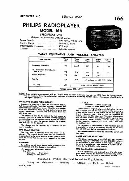
Extracted text from philips 166 service manual (Ocr-read)


Page 1

RECEIVERS A.C.

PHILIPS RADIOPLAYER

MODEL 166
SPECIFICATIONS

(Subject to alteration without notice)
ZOO-ZSOV. 40-50 5/5.
5304620 kc/s.

Power Supply . ,. ......
Tuning Range .I ., I . , ......
Intermediate Frequency

Cabinet , , , , ,.. ......

455 kc/s.

SERVICE DATA

Bakelite mantel

VALVE EQUIPMENT AND VOLTAGE ANALYSIS

- Velve Valve Plate 03:. 5
Valve Function Na. I TYPI I Volts Volts WIN
Frequency Cmverter VI MN? ZIO 55 55
LF, Amplifier, Demoduletar
and A.V.C V2 5N8 2I0 55 '-

Power Amplifier v3 6M5 203 210 -
Rectifier V4 I 6V4 V4 uthode - LIB C,T.. 232V.
Dill Lamp VII l 6.3V, 0.3% tubular screw

Voltage amass R13, -6.7V

NOTE: These voltages are melwrud with an "LOGO ohms per volt" meter and may vary a: 10% from the figures quoted.

W are meemred
no alone!" condition.

To IIMOVE CHAS FIOM CAIINII'.

Remove the power plug hem the wall outlet diet.
Pull the emu-vi knobs hum their spindles. Know the
:ornbined bark and bottom covers Unsolder the speaker
voice coil mnnections fmrn the lug strip alongside the
output melormer Unwind the dial cursor from the
dial drive cord.

The dash is held to the cabinet by two screws er
the mar. Removal of these two screws and the associated
mounting brackets and packing pieces allows the dusk
to be withdrawn horn the ubinet leaving the weeker
and dial scale in the abinet.

The drum may be replaced by a reversal of the
above procedure.

DIAL SCALE REMOVAL

The dial sale is removed from the front of the
cabinet. The control limbs must first be withdrawn.
In ramming the dial scale securing screw, care must be
taken Ito mu that dam-gs la not caused to the meals
by toes.

ALIGNMENT.
By making use of short length tools, alignment can
be undertaken with the chasm in the cabinet.
LFI herstormer ediuttrnent: ere:-
2r\d I.F.T.-
Secondary _ front screw
Primary - rear xcrew

the socket points indie-ted to dual: or acrcee the mister: listed. The rec-ire! should be h e

Ist I.F.T.-
dary - screw nearer 6N8
Primary - screw Mill! SAN?

Before commencing R.F. alignment, fully cluse the tun-
Ing cap-cits: and set the dial minor to the stop mark
which will be found at the bottom of the dIeI scale It
the low trequenw end. Use an 100 pF capecltor es
dummy aerial for R.F, alignment. Trimming adjustments
are: milletur trimmer (I320 Ice/s. 3XY) front nI tun-
Inn apedtor, aerial trimmer H.420 kit/s) rear of
tuning opacitory padding 600 kelr, 72L) iron cure
in oscillate! mil.

in the event of replacement at the ascilI-lor cell. It
in advisable to make a orellminary peaking at the Iron
core at 600 kc/x before documenting alignment.

No attempt ell-arid be rude te alien re. eerIeI coil
Iron m.

MAINS VOLTAGE ADJUSTMENT.

The power transformer 11 pmvided with two primary
winding teppirrgs-lOO/ZSO volt: end 240/250 volt!-
tor ediustmlnt at the receiver to the supply voltage at
the point of installation. The receiver ls adjusted at the
factory to the 240/250 volts upping.

DIAL CALIIRATION ADJUSTMENT.

It dial cellbretlons are incorrect over the dial sale
by an eeuel amaunt, the error can be corrected by sliding
the cumr on the dial cord tv the correct position.

Published by Philips Electrical Industries Pty. Limited

Sydney - Melbourne -

MARCH, I953

E risbane

--- Adelaide -

Perth Hobart

ILA-arr a near mm