Philips 15 rb 697 service manual

This is the 6 pages manual for philips 15 rb 697 service manual.
Read or download the pdf for free. If you want to contribute, please mail your pdfs to info@audioservicemanuals.com.

Page: 1 / 6
left right
philips 15 rb 697 service manual

Extracted text from philips 15 rb 697 service manual (Ocr-read)


Page 1

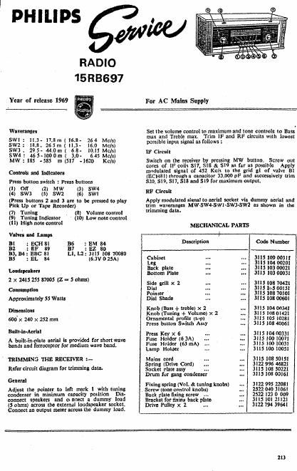
PHILIPS ,

RADIO
15RB'697

For AC Mains Supply

Year of release 1969

Waverange; Set the volume control tr+maxilmumgngéone controls "1) Bass
max and Treble max. rim F an circuits with owest

SW1: 11,3- 17.8m(16.8- 264 Mc/s) c' ;

swz : 18.8. 265 m ( [1.3- 16.0 Mc/s) pnsblempmssml mum's

SW3 . 295- 440m ( 6 8- 10.15 Mc/s) u: Circuit

swa : 46 5-1000m ( 3.0. 6.45 Mcls) . ,

MW : 185 -585 m [517 -1610 Kels) Switch on the receiver by pressmg MW button. Screw out

cores of IF coils 317, $18 & $19 as far as possible Apply
modulated signal of 452 Kcls to the grid g1 01' valve 81
(ECHSI) through a canacitor 33.000 9F and successively trim
520, $19, $17, 518 and 819 for maximum output.

Controls and Indicators

PreSs button switch : Press buttons

(1) Off «2) Mw (3) SW4

(4) SW3 (5) SW2 (6) SW1

(lfress buttons 2 and 3 are to be pressed to play
Pick Up or Tape Recorder)

(7) Tuning (8) Volume control
(9) Tuning Indientor (10) Low notecontrol
(11) High note control

RF Circuit

Apply modulated simal to aerial socket via dummy aerial and
trim waverangn MW-SW4-SWl-SWJ-SW2 as shown in the
trimming data.

MECHANICAL PARTS

Valves and lamps

Bl : ECH 111 36
B2 : EF 89 B7
B3. 34: BBC 81
B5 : EL 1%

: EM 34

:E2 80

L1, L2: 3115 108 10080
(6,3V 0 25A)

Loudspeakers
2 x 2415 255 87005 (2 - 5 ohms)

Consumption
Approximately 55 Watts

Dimensions
soox 240 x 252 mm

Built-iu-Aerial

A built-implore aerial is provided for short wave
bands and terrocepx or for medium wave band.

' TRIMMING THE RECEIVER :-
Refer circuit diagram for trimming data.

General

Adjust the pointer to left mark 1 with tuning
condenser in minimum capacity pontion Dis-
connect speakers and cinrtect a dummy load
(5 ohms) across the extemai loudspeaker socket.
Connect an output meter across the dummy load.

Code Number

Description
Cabinet
Leg
Back plate
Bottom Plate
Side grill x 2
Dial .
Pointer
Dial Shade

Knob (Bass + treble) x 2
Knob (Tuning + Volume) x 2
Ornamental profile (tup)
Press button Switch Assy

Press Key x 6
Fuse Holder (6 3A)

Fuse Holder (63 mA)
Lamp Holder

Mains cord
Spring (Drive Cord)
Socket plate assy

Drum for gang condenser

Fixing spring (Vol. & tuning knobs)

, Screw (tone control knobs)

Back plate fixing screw . .
Bracket for fixinr back plate
Drive Pulley x 2 ..

311510900311
3115104 0020]
3115 103 00021
3115 103 00031

3115 108 70421
31151:.5 00151
3115108 70101
3115 108 00601

3115 104 0034!
311510801421
311510510281
311510840061

311510400331
3115 10010071
3115 10010031
311510010051

3115108 50151
3122996 46821
3115 108 50221
3115108 00161

3122 995 22081
2522 040 31061
2522 123 0 009
311510121121
3122 794 39641

113