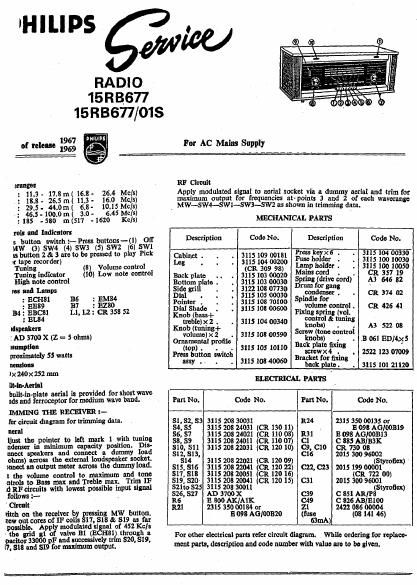
Philips 15 rb 677 service manual

This is the 8 pages manual for philips 15 rb 677 service manual.
Read or download the pdf for free. If you want to contribute, please mail your pdfs to info@audioservicemanuals.com.

Page: 1 / 8
left right
philips 15 rb 677 service manual

Extracted text from philips 15 rb 677 service manual (Ocr-read)


Page 1

'HILIPS

RADIO
15R3677
15R3677/015

For AC Mains Supply

1967 014111051
of release 1969 1
mes

: 11.3- 17.8m( 16.8- 26.4 Mc/s)
18.8 - 26.5 m( 11.3 - 16.0 Mcls)
: 29.5- 44.0m( 6.8- 10.l5 Mclsl
: 46.5-100.0m( 3.0- 6.45 Mela)
:185 -580 1n(517 -1620 Kc/s)

rain and Indicators

5 button switch :- Press buttons-(l) Off
MW (3) SW4 (4) SW3 (5) SW2 (6) SW1
1: button 2 k 3 are to be pressed to play Pick

1: tape recorder)
Tuning (8) Volume control
Tuning indimtor (10) Low note control
High note control
vol Ind anpl
: ECHtll
: BB
134 2 EBCS]
: EL84
Idspenkerl
:AD 3700 X (Z = 5 ohms)
umprlon
proximatew 55 watts
nenslons
)x 240x 252 mm

ilt-ln-Aerlnl
built-in- late aerial is provided for short wave
11d: and erroceptor for medium wave band.

IMMING THE RECEIVER :-
Ier circuit diagram for trimming data.
nernl '
[just the pointer to left mark 1 with tuning
ndenser in minimum capaoity position. Dis-
meet speakers and connect a dummy load
ohms) across the external loudspeaker socket.
mnect an output meter across the dummy load.
1 the volume control to maximum and tone
ntrols to Bass max snd Treble max. Trim IF
0 RF oircults with lowest possible input signal
follows 1' ,
Circuit
vitch on the receiver 15 greasing MW button.
mew out cores of IF eoi 5 l1, SIB a $19 as far
possible. Apply modulated signal of 452 K11]:
the grid ul of valve Bl (BCHBI) through n
1 itor 33000 p? and successively mm 520, 519.
l . $15 and $19 for msxrrnum output.

136 : EM
B7

:BZBO
Ll.L2: CR35852

RF Circuit

Apply modulated signal to aerial socket via a durum serial and t '
maximum output for frequencies atpoints 3 and 2y of each 1333152:

MECHANICAL PARTS

_ MW-SW4--SWl--SW3-SW2 as shown in trimming data.

Description Code No. Description Code No.
gm. 311210933181 502w; 21121231232
8 (339 92g" Lamp holder . 3115 101110050
Back plate .. . 3115103 00020 a?!" W? - - CR 357 19
Bottom late . . 3115103 00030 Spun] (dnve cord) A3 646 82
Side 3111 . 3122 103 07730 mm M 9"
Dinl . . 3115105 00030 5 $3110?" - - CR 374 02
333336 - - 3;}; {3: 33133 " voiimimox cr 425 .1
Knob (hass+ . Fixing fin. (21' .
$1513; n2g ; 3115 104 00340 1:331:13: 1 A3 522 08
1 . .
volumc) x 2 . 3115 103 00590 5 m MW
0mm, mm 11 k 0 t) . . .13 051 1311/4555
top . . . . 311510510110 ° Puma"
Press button swrtch Bmfilgtagfifix'lng 2522 123 07009
as . -
Y - 5 1° 40 backplate. . 3115101 21120
ELECTRICAL rum-s
Part No. Code No. Part No. Code No.
sr,s2, s3 3115 203 30031 1124 231 350
54, SS 3115 2011 24031 (CR 13011) . 5 3090:13151/3'01119
ss, 57 3115 205 24021 (CR 110 or) 1131 13 0113 1101010313
ss, 59 3115 203 24011 (CR 110 07) Cl C 885 11131:
510, 511 3115 201122031 (CR 12010) cg, C10 C11. 730 05
512, 513, C15 2015 300 95002
s14 3115 205 22021 (CR 120 09) (Styroflex)
s15, 515 3115 205 22041 (CR 120 22) c22,023 2015199 00001
511, 310 3115 203 20051 (CR 120 15) CR 722 00)
s19, s20 3115 208 20041 (CR 120 15) 031 2015 130095001
52110 525 3115 203 30011 Styrotlcx)
$26, 521 AD 370011 C39 c 551 Anni
115 11 1100 AKIAlK as c 1125 1113111100
R21 2315 3103 (3091352 310013 z1 2422 055 00004
20 (fuse (05141 45)
631nA)

For other electrical. parts refer circuit diagram. While ordering for replace-
ment parts, description and code number with value are to be glven.