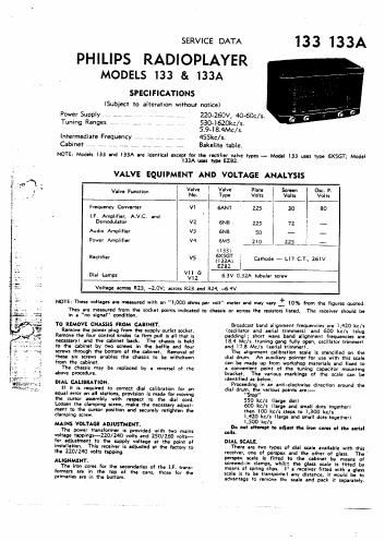
Philips 133 133 a

This is the 4 pages manual for philips 133 133 a.
Read or download the pdf for free. If you want to contribute, please mail your pdfs to info@audioservicemanuals.com.

Page: 1 / 4
left right
philips 133 133 a

Extracted text from philips 133 133 a (Ocr-read)


Page 1

SERVICE DATA

PHILIPS RADIOPLAYER
MODELS 133 & 133A

SPECIFICATIONS

(Subject to alteration without notice)

133 133A

Power Supply ZZO-ZSOV, 40-60c/sl
Tuning Ranges SSO-IGZOkC/s,

5l9-I 3.4Mc/s.
Intermediate Frequency 4SSkc/s.

Cabinet .. , Bakelite table.

Nora; Models 133 and ISSA m identlul axupt for Ihc uptitiar valve typas - Modal In use: type EXSGT; Modal
ISSA we: type E232

VALVE EQUIPMENT AND VOLTAGE ANALYS|S

. Valya Valve Pleta Smart cu, P.
W" mm" No. Type Volts , Volts l Volts
Frequency Converter v1 6AN7 225 l 30 l 80
LF Amplifier, A.\/.C. and I
Demadulator v2 ENE 22; l 72 l _
Auaia Amplifier v3 1 6N8 so _ I _
Power Amplifier v4 I 6M5 ZI_0 A35; 7* _
twat
l x5 4
nsrtlher v5 33 Calhpda - LI'I C.T., 261V
£232
m VII 5
al Lamps VIZ svsv can tubular anew
Voltage 8m R23, -2.0V, moss R15 Ind R141 -6,4V

NOTE: These voltage: In measured with an "LOGO ohms per volt" meter and my no] 1 I056 4mm the figures quoted.

They

in.

o Sigul" mlflma

To REMOVE CHASSIS riloM CABINET,

Remov- the power plug from the supply outlet socket.
Remm: the ion! control knob: ia firm pull it all that is
mm and the sabinst badt. Th. chassis is held
to m cabinet by two screw: in tin. hams and tour
straws throw. iha bum pi lhe ubtnel. karmal 0!
ohm SIX mm arr-bias th. chassis to la. wIthdrawn
from the bin".

Th. chassis may be rcplacad by a marsal at the
alloys pmldure.

DIAL ULIIMTION.

If It is required to correct dIil calibration lot an
equal error on all stations, provision is made tar moving
the cursor assembly with aspen to the fill 90M,
Loosen th. clamping :ruw, make tilt necesury adjust.
ment to th- cursor pasition and manly «tighten tin
clumping screw,

MAINS VOLTAGE ADJUSTMENTl

The power transform" is pmidad will-l two main:
twinge tnppinus-ZlO/ZM) volts and 250/260 volts-
lur adjustment to ttts supply voltage at thu point or
installatlun. ThIs mu it adlusted at the lactory to
tha 220/240 volts tapping.

ALIGNMINT.
The Iran cores for the secondaries of the LR truis-

lormer: Ire in the top of the can: thus: hr the
primaries are in th- battm

mellured hum the socket points indicated Io chew! Dr urns the "sister: lined, The receiver should be

Brnadnasl band alignment frequencies are 1,420 kc/s
(maillalor Ind aerial trimmers) and 500 kc/s (slug
padding) ; short wave band lllfinmenr frequervcin at:
ISA Ms/s [tuning gang tuliy open, oscillate" XvimmerI
and 17.8 Mc/s (aerial lriminerl.

The alignment alibulion ml. is slenellied an the
dial drum. An lulu .ary pointer for use with this scale
can la. in a. up truth workshop matarlals and fixed to
a canvan at point of tha tunlnp capacitor mounting
bracket. Th- various writing. or the seal: can be
identified as below.

Proceeding in In unlisclockwiu direction I'Wfld lb:
dial drums, in. various poinls an:-

l, m ,,

550 kzls (l-rg- doll
600 kc/s we md small dots together)
then 100 Incl: slept to I300 kc/s
L420 its/s llarga Ind small data tog-than
1,500 kc/s
F: not Alta-pt Io allim III iron com of tin auial
IL

DIAL SCALE.

There are two types .1! riial ml: available with this
receiver, one or pemx and the other or plass. Thu
perspex scale I: titted In tile cabihat by means at
screwed-in clamply whim the glass asale is filled by
means at spring clinst I a melt/er tilt-d with a glass
scale is to l:- tiansponel any diiunce, it would be to
auvahtape to remove th. kale and pack it separately.