Philips 132 service manual

This is the 4 pages manual for philips 132 service manual.
Read or download the pdf for free. If you want to contribute, please mail your pdfs to info@audioservicemanuals.com.

Page: 1 / 4
left right
philips 132 service manual

Extracted text from philips 132 service manual (Ocr-read)


Page 1

SERVICE DATA

PHILIPS RADIOPLAYER

MODEL 132

SPECIFICATIONS

[Subject to alteration without notice)

Power Supply .

Tuning Ranges 7.

Intermediate Frequency

Cabinet .. H H r.

220-260 volts 40-60 c/st

$304,620 kc/s.
5348.4 Mc/s.

455 kc/s.

Bakelite table.

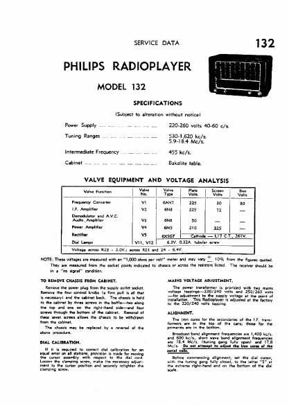
VALVE EQUIPMENT AND VOLTAGE ANALYSIS

W Fm°" l VJ? 43; I $5: I 55275;" i 331;
Frequency Converter v1 GAN'I I 225 30 so
l.F. Amplifier A v2 6N8 225 72 -
Demoduletor .nd A.v.ct I
AudloAmplllier v3 6N8 so _ _ _
Power Amplifier V4 6M5 210 225 i _
Miler VS 5x551 W
Dial um.» vu. v11 6.3V. 0.325.. 51391.: 1:
Voltage was 1:23 . 2.ov.; across R23 3nd 24 . 5.4V.

NOTE: The" voltages are measured With an LOGO ohms per volt meter and may VH'Y : 10% {rem the figures quotedr
They are measured From the socket points indicated to chassis or across the resistors listed. The rgcgiygr should be

In a "no signal" condition.

To REMOVE CflASSIS FROM CAIINET.

Rtmove the pewter plug from the supply outlet socket,
Remove the tour control knobs (a firm pull is all that
is unwary) Ind the abth back. The chassis is held
to the ublmt by thin screws in the bafllktwo along
the top and one on the right-hand side-and tour
screws throth the bottom of the cahinet. Rot-loyal at
these seven screws allows the chmis to be wilttdnwn
hunt the ablnetv

The chassis my be replaced by a revlrsal at the
above procedure.

DIAL CALIBRATION.

It it ls "(wind to correct dlnl calibration for an
equal error on ell stations. provision is made tor manna
the cursor assembly with respect to the ass: cord
Loosen the clamping screw, make the necessary adiust-
meat to the tumor position and securely retiqhten the
clamping screw.

MAINS VOLTAGE ADJUSTMENT,

The power transformer is pmvldad with two main:
voltage tappings-ZZO/Z40 Volts and 250/250 volts
-Ior adiustment to the supply voltage at the point of
installation. This Rldloplayer is adjusted at the lsetory
to the 120/240 volts tapping.

ALIGNMENT.

The iron cores for the secondaries at the LF. trans-
tormars Ire in the top of the cans; those to:- the
primaries are in the bottom.

Broadcast hand alignment irequnnsies an L420 kc.
and 600 kc/sfl short w-ve band alignment frequencies
are 18.4 Mcls. (tuning gang fully open) and .8
Mc/st Do not oltemnt to ldiull II that earn- al the
nth :

new. Emmeneing alignment at the dial cursor,
with the tuning gang lully closed, to the letter "S" at
the extreme fight-hind end on the bottom at the dial
sale.