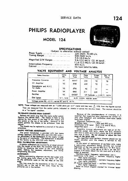
Philips 124 service manual

This is the 4 pages manual for philips 124 service manual.
Read or download the pdf for free. If you want to contribute, please mail your pdfs to info@audioservicemanuals.com.

Page: 1 / 4
left right
philips 124 service manual

Extracted text from philips 124 service manual (Ocr-read)


Page 1

SERVICE DATA

PHILIPS RADIOPLAYER

MODEL 124

SPECIFICATIONS

Power Supply
Tuning Ranges ., .

Magnified S/W Ranges

Intermediate Frequency

(Subject to alteration without notice)

ZZO-ZSOV, 40-60 c/s.
5304620 kc/s.

5.94 8.4 Mc/s,

9440.0 Mc/s (3] M band).
[1,442.0 Mc/s (25 M bandl.
455 kc/s.

Cabinet .. . De luxe bakelite table.
VALVE EQUIPMENT AND VOLTAGE ANALYSIS
. V Ive Valve Plate Screen Osc. Pt
Valve Function ! 30. T ync Volts l V cits I Volts
Frequency Converter 1 VI 6AN7 I 230 l 72 I 75
LP. Amplifl'ar : v2 6N8 230 70 ~
Demomlator and AAV.C. I
lit Audio I vs ENE 46 ll _
Power Amplifier I w 6M5 zll Lao _
Rectifier vs 0661' v5 Cathode - LIUC. ., 267V
Dial Lapin Vl l, vxz 6.3V. 0.3%. tubular screw
Voltage across R8, -2.lV.;Vaeross R7 and 5, -6.7V. I

NOTE: Thea. voltages are nleasured with an "1,000 ohms per volt" meter and mly vary i 10% from the tigures quoted,
Thry are measured from the socket points indicated to chassis or across the POSIafOfS listed. The receiver should be

in a no signal" condition.
1'0 REMOV CHASSIS FROM CAIINET.

Rernme the power plug from the mains outlet socket.
Remove the cabinet back. The chasix is held to the
cabinet by {our screws in the base of the chassis and
tern KI'IVS at the top of the baffle. Removal of the
renews namlts the dusts to be withdrawn from the
chiner.

The chants may be replaced by a reversal ml the above
procedure.

MAINS VOLTAGE ADJUSTMENT.

The power transformer is mvlded with two main;
voltage timings-220nm volts and 250/260 volt:-
for adjustment of the Radiualayer to the supply voltage
at the point at innullatlon. The Radloolayer is adjusted
It the famy to the 210/140 volts tapping.

DIAL CAUIRATIW ADJUSTMENT.

It at on ulibntions an incorrect by an equal amount
ever the Ianath of the scale, the condition may be cot-
rented by loosening the cursor to dial cord clamping
mu, makmg the necessary adiusiment, and firmly
mtiahtanlng the screw.

ALIGNMENT.

Before commencing alignment set the dial cursor with
the tuning gang Iully closed to the letter "5 mark
onlthl calibration scale on the top edge of the dial
aca a.

The Iron cores for the secondaries of lha LF. trans-
fnrmers are in the ton at the cans; those tor the
pflmariu are in the bottom.

Because (If the interdependence of trimmers, it IS
essentlal that magnified bend alignment be carried out
only after broadcast and continuous short-wave bands
have been aligned.

Allprll'nent frequencies are ,-

Bmtdcast band .. ,, L420 and 600 kc/s.
Continuous SIW band I81, 174 and 6 Mc/s.
Magnified band . .. .. ll.a Mic/sr

Capac ye trimmer adinstrrlenta are used at all tre-
quenc-es except 600 kC/Sr, where the BIC oscillator
iron core is used; and 6 Mo]: where the S/W oscillator
iron core is used. Do not attempt to adiun the im-
caru of the aerlll coils.
The magnified band «clllatar trimmer should not be
finally adusted until the draw: is refitted to the
cabinet.
In in. event of replacement or oscillator milxy min
a preliminary adiustment before carrying out normal
allgnment ol the iron core at 600 kc/s. fur B/C band.
and with the dial cursar nt.at 6 Male. on the con-
tinuous S/W band, admit the iron core until a 6 Mela.
signal I: received.
Oxlllltor/signal frequency nlaticruhlps are:-
Continuous S/w band - oscillator Frequency higher
than signal frequency.

31 metre! magnified band 7- mill-tor frequency higher
than signal frequency.

25 metres magnified band - alcilktor frequency lower
than signal Frequency.

Refer to circuit diagram overleaf for trimmer layout
drawlng.