Philips 117 service manual

This is the 4 pages manual for philips 117 service manual.
Read or download the pdf for free. If you want to contribute, please mail your pdfs to info@audioservicemanuals.com.

Page: 1 / 4
left right
philips 117 service manual

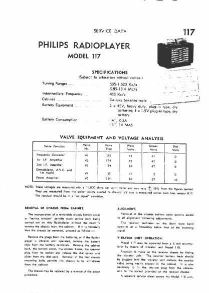
Extracted text from philips 117 service manual (Ocr-read)


Page 1

SERVICE DATA

PHILIPS RADIOPLAYER

MODEL 117

SPECIFICATIONS

(Subiect to alteration without notice]
$354,620 Kc/s
5.85484 Mc/s .. .

455 Kc/s h ..
De-que bakelite table

Tuning Ranges .

Intermediate Frequency
Cabinet .....

Battery Equipment .

Battery Consumption

M

2 x 45V, heavy duty, pIGg-in t pie, dr
Y Y

batteries; I x 1.5V plug-in type, dry
battery

"A, 0.3A
"8". l4 MAS

VALVE EQUIPMENT AND VOLTAGE ANALYSIS

W at I 11': $2.: 5327:: 5:;
Frequency Converter VI I ms 41 41
Ist LF. Amplifier v2 I m 47 47 _
1nd LF. Amplifier I vs I m 84 47 o
Demoaulmr, A.V.C. and ' I
m Audlo v4 I I55 7 I7 5 a
Power Amplifier i v5 354 I s; 57 -6

NOTE: These voltages are measured with a "LOGO ohms per volt meter and may vary '1: l0% from the (lg-ire; wanted.
They are meamred (tom the socket points quoted to chassis: VS bias is measured across back bias resistor R17.

The receiver should be in a "no signal" cvnditiun.

REMOVAL OF CHASSIS FROM QUINN.

The Mutton at a removable chassis bottom never
at "service window" permits much service work being
atriod out on this Radinplayer without the need re
remove the chassis Item the cabinet If It is necessary
that the chassis be removed. proceed as Inflows:-

Remave the plugs from the batteries, or if the Radio<
player is vibrator unlt operated, remove the batterv
clips Item the battery terminals. Remove the cabinet
back, the bottom adv-r, the control knobs, the speaker
plug from its socket and release the dlal cursor and
slider from the dial cord. Removal at the {our chassis
mounting bolts permits the chassis to be withdrawn
from the cabinet.

The chassis may be replaced by a reversal of the alsoVe
procedure.

ALIGNMENT.

Removal at the chassis bottom caver perrrtt'ls aecess
to all allgnment trimming adjustments
The receiver ascIIIetor on the short vrave band

Operates at a frequency below that of the inctrmina
signal.

VIIRATDI UNIT OPERATION.

Model I17 may be operated from a 6 vult accumu-
Iator by means of vibrator unit Model IIB.

Provision is made on the receiver chassis for fitting
the vibratur unit. The receiver battery toads should
be plugged Into the Vlbrlmr unit sockets, the surplus
sable being neatly stowed in the cabinet. It i: also
necessary to lit the two-pin plug tram the vibrator
unit to the seeker provided an the receiver chassis.

A separate service sheet covers the Model Ila untl.