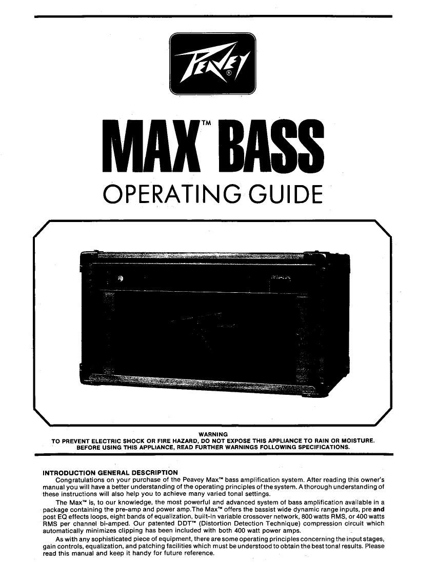
Peavey Max Bass Operating Manual

This is the 6 pages manual for Peavey Max Bass Operating Manual.
Read or download the pdf for free. If you want to contribute, please mail your pdfs to info@audioservicemanuals.com.

Page: 1 / 6
left right
Peavey Max Bass Operating Manual

Extracted text from Peavey Max Bass Operating Manual (Ocr-read)


Page 1

MAX BASS

OPERATING GUIDE

J -

WARNING

TO PREVENT ELECTRIC SHOCK OR FIRE HAZARD, DO NOT EXPOSE THIS APPLIANCE T0 RAIN OR MOISTURE.
BEFORE USING THIS APPLIANCE, READ FURTHER WARNINGS FOLLOWING SPECIFICATIONS.

INTRODUCTION GENERAL DESCRIPTION

Congratulations on your purchase of the Peavey Maxm bass amplification system After reading this owner's
manual you will have a better understanding of the operating principles ofthe system A thorough understanding of
these instructions will also help you to achieve many varied tonal settings.

The Max" is, to our knowledge. the most powerful and advanced system of bass amplification available in a
package containing the preamp and power amp.The Maxl offers the bassist wide dynamic range inputs, pre and
post EQ effects loops, eight bands of equalization, built-in variable crossover network, 800 watts RMS, or 400 watts
RMS per channel bi-amped. Our patented DDT" (Distortion Detection Technique) compression circuit which
automatically minimizes clipping has been included with both 400 watt power amps.

As with any sophisticated piece of equipment, there are some operating principles concerning the input stages.

gain controls, equalization. and patching facilities which must be understood to obtain the best tonal results Please
read this manual and keep it handy for future reference.

Page 2

B
8
4

Hmna'flnc
450:
or o

: L
e g e

Z
11
S
61" m o:
20 en
ZS z:
E m A
r11
1] II
D
5 m _i
3 l m \ (I)
E
l to Z

at
5
S

wouos
gb
so: s

HE»
S

ZLEL
5 E

HDNfid
+m 3:»-
ag: e

S

ADDS

oer 5L-
5 5
a 9

age

55
S

at at

at EL
5

auewu
tfil 9%
50: e

ALIHVlD
«5» SL-

5» at,

e a s s

s _ e a
EOE:

'EL Qt-
SEE

El

at EL
5

BaNasaHd lHBItIE
El. EL
5 E
8

St El-
ei er
5 E
9 a
euro

2903
9; St-
ag: 8

EL
5
9

X7 >ia L GUS use CiaL DB
SEI MOI -'

>18

'- NOLLVZI'IVI'I

- NDILVZIWVI'IEE HSIH -

L

ADNaniflEitdd

ELL
HEADSSDHC}

WELSAS
Nouvoianawv
seesaw-innw

0 nu

3:40

DE

XVW

+
'ONE)

ND
'eiMd

FRONT PANEL

THE INPUTS .

The Max" has two inputs labeled high gain and low gain. The high gain input is the input which should
normally be used and would deliver the highest signal level from the input to the preamp. Sometimes however,
bass guitars that are equipped with very high output hot" pickups. or built-in preamps will overload the high
gain input. This will be apparent because you will hear distortion. If this distorted sound does occur, plug your
instrument into the low gain input which has less gain (-GdB) then the high gain input. When two instruments or
signal sources are plugged into both inputs, the high gain input is automatically switched to the same level as
the low gain input. NOTE: When using two instruments or signal sources we strongly recommend that the
volume controls be set at a reasonably low volume level to reduce the possibility of undue distortion and/or
speaker damage.

\ THE GAIN SECTION
THE PRE GAIN CONTROL

The pre gain control is the first volume control of the system. If the post gain control is set to its full number
ten position for maximum power reserve. the pre gain control should be positioned somewhere in the middle of
its range or lower, Placing the pre gain control higher than five may cause unwanted square waves (distortion)
and result in premature clipping and/or activation ofthe DDT" compression circuitry, The pre gain control also
employs a pull bright switch which adds approximately 3 dB of boost to the high end. As with the 4 Hz and 8 Hz
rotary controls located in the equalization section, the pull bright swltch can be used to enhance many at
today's modern bass playing techniques.

THE POST GAIN CONTROL

In normal use. the post gain control should be operated above the 12 o'clock or number five position. To
obtain maximum power reserve and headroom. rotate the control tully clockwise to number 1 0. NOTE: With the
post gain control at its number 10 position. the pre gain control should not be operated above its 12 oclock or
number five position to avoid unwanted distortion Also, while using maximum power and extreme high end
boost in the equalization section you may find it necessary to back down (cut) the post gain control to
approximately its number eight to avoid any unwanted residual noise,

The post gain control also utilizes an integral pull switch labeled punch"t When activated, punch creates
a boost at 120 Hz and adds dramatically and effectively to the low end response and projection capabilities of
the Max'fi

THE EQUALIZATION SECTION

The Max" contains eight individual controls for shaping and contouring the instrument signal. Please be
aware that these equalization controls employ active circuitry allowing you to have complete and accurate
cut/boost capabilities of highs (treble). mid-band frequencies, and lows (bass). Because these controls are
active. the equalization section can give you an accurate representation of the "natural" sound of your
instrument without undue coloration by simply placing all eight controls at their 12 o'clock orzero positions.
Rotating the controls to zero renders the system flat" and is an excellent place to start when you begin to look
for new tonalities and sounds.

Notice that the eight equalization controls are divided into two sections - low equalization and high
equalization with each section containing fourseparate bands labeled in two ways for ease of operation. Above
each control is a number stating its center trequency and below each control is the description commonly used
to describe the tonality or sound of each band. The following explanation of each control andwill serve as a
general guideline to acquaint you with the Max""s equalization section.

THE LOW EQUALIZATION SECTION

The four bands of the low equalization section consist of four knobs whose frequencies are centered at 60
Hz (bottom). 120 Hz (punch), 250 Hz (body). and 500 Hz (timbre).

The 60 Hz/bottom control serves to contour the extreme low end (bass) response of the system. In high
volume situations, it may be necessary to reduce (cut) this control~ as low frequencies tend to absorb more
headroom (available power) from the power amp. NOTE: Over boosting of the 60 Hz/"botlom" control may
cause unwanted distortion at the loudspeaker and/or engaging the DDT" circuit on a constant basis This
problem can be corrected by setting the control flat (placing the 60 Hz/bottom control at zero) or reducing the
system to any of the minus positions.

The 120 Hz/punch control is the element which should be used when extra projection of the bass guitar
signal is required and it will also give the appearance" of more bass response. As with the 60 Hz control, over
boosting of this control in high volume situations may cause occasional lighting of the DDT" control. If this
occurs render this control flat and/or set it to the minus (-) positions.

The 250 Hz/body control is useful for tailoring the fundamentals (basic pitches) on the middle portions of
the bass guitar register. The 250 Hz/body control also adds a fullness to the overall sound of musical styles suCh
as rock,

The 500 Hz/timbre control is set at the mid to high points of the bass guitar spectrum allowing you to
easily obtain the fatness necessary in rock (boost positions) or the tight. well defined tonalities found in jazz
and country styles (cut positions).

THE HIGH EQUALIZATION SECTION

The high equalization section consists of tourcontrols centered at 1 KHz (clarity"). 2 KHz ("bright"). 4 KHz
(presence"). and a KHz ("edge").

The 1 KHz/clarity control. in coniuction with the 500 Hz/timbre control ofthe low equalization section. can
be used in its boost position to help obtain many of today's funk styles and. in thecut position. help round out
the upper mids to give a characteristic acoustic" sound to the bass guitar.

The 2 KHz/bright control begins the upper end" tailoring to either add or substract many ofthe overtones
for the brigthening or softening of the sound of the instrument. It is also useful for tailoring the high frequency
section while using the Max" in bi-amp situations.

The 4 KHz/presence and 8 Hz/edge controls are the final controls in the high equalization section and
serve to adiust the extreme upper end response of the Max". In their boost positions. thev will enhance modern