Parasound hca 2200 mk2 owners manual

This is the 12 pages manual for parasound hca 2200 mk2 owners manual.
Read or download the pdf for free. If you want to contribute, please mail your pdfs to info@audioservicemanuals.com.

Page: 1 / 12
left right
parasound hca 2200 mk2 owners manual

Extracted text from parasound hca 2200 mk2 owners manual (Ocr-read)


Page 1

Placement of your HCA-2200II Keep your Parasound HCA-2200II out of direct sunlight and away from windows which could ever be left open to let in rain. It should be placed away from heat sources such as hot air ducts or radiators. Make sure your cabinet or shelf can support its weight! Do not place the unit directly on a pile carpet that could interfere with air flow into its bottom vent openings or heat sinks. If you place the HCA-2200II on the floor near your speakers, put it on a piece of wood to elevate it above the pile of the carpet. If you stack your components, it is better to place the HCA-2200II alongside your other components. The HCA-2200II is biased well into Class A, resulting in noticeably warm operation which could disturb components stacked on top of it. If it is inside a cabinet, allow ample ventilation. Very sensitive low level sources placed too close might pick up some hum radiated from its enormous powersupply. Rack Mounting the HCA-2200II The HCA-2200II can be mounted in a standard EIA 4 unit 19" rack. Make sure you select heavy duty mounting bolts and nuts and use washers under the heads of the bolts to avoid scratching the amplifier's anodized front panel. Do not attempt to hold the unit in place yourself while you attach the bolts and nuts - have someone support the unit while it is being attached to the rack. Making Connections Before making any signal or speaker connections, make sure your power amplifier is turned off. When making connections, make sure there is no strain or tension on input leads or speaker wires that could cause them to pull loose later on. lnput connections In most stereo systems, you will use the gold-plated RCA jacks for the Right and Left channels. Make sure these are consistent with the right and left outputs from your preamplifier. For professional applications you can use the alternate XLR (often called "Cannon") input connectors. The XLR inputs are for balanced lines whose ground is a third wire, separate from the audio signal + and - wires. The HCA-2200II employs this industry standard pin configuration: Pin 1 Ground Balanced signal lines are preferred for long signal runs to reduce hum pickup Pin 2 + signal They are also useful in areas where excessive RF or 60 Hz television Pin 3 - signal broadcast synch. signals might interfere. Some of the finest high end preamplifiers, including the Parasound P/FR-2000 and P/LD- 1500, provide balanced line outputs. If your preamplifier is so equipped, you may prefer to use the balanced connections which increase immunity to external noise. Be certain to check the pin configuration for your preamplifier's balanced line outputs and, if neces- sary, reverse the wires at one end of the right and left cables so each preamplifier + goes to the HCA-2200II +; each preamplifier - goes to the HCA-2200II's - ; each preamplifier ground goes to the HCA-2200II ground. Note Balanced/Unbalanced lnput Select Switches Select the inputs, XLR or RCA jack, which you have connected to the HCA-2200II Do not change the left and right channel input selector switches while the amplifier is operating!

Page 2

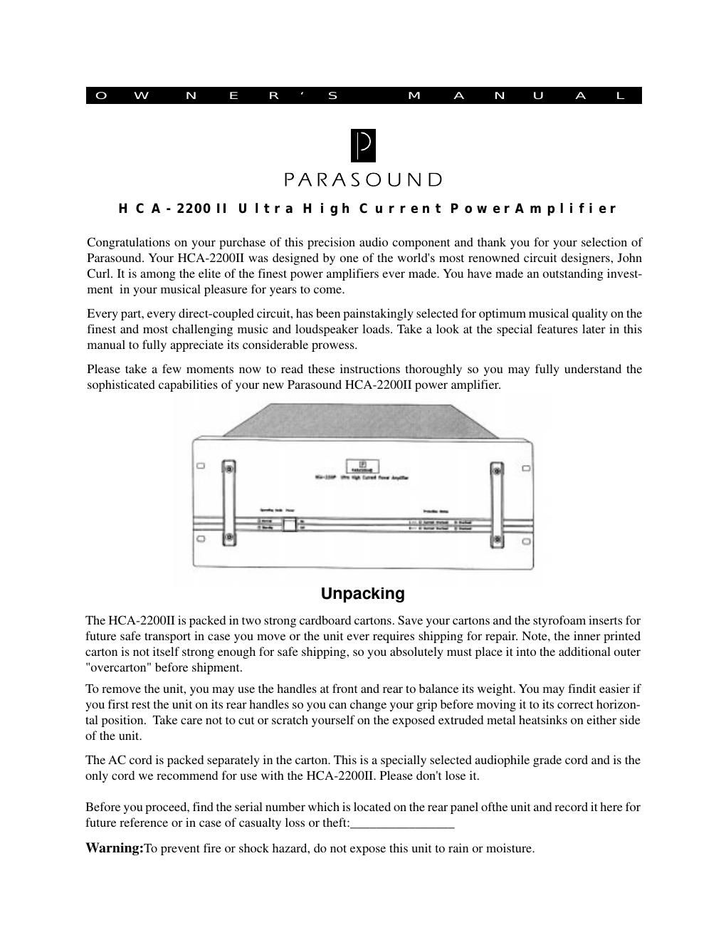
Rear Panel 1. Input Jacks - RCA type for unbalanced lines 2. Input connectors - XLR type for balanced lines 3. Input selector switches - balanced or unbalanced inputs 4. Mono Bridging Selector 5. Speaker Terminals6. Main Fuse 7. AC Power cord receptacle 8. Right channel B+, B- rail fuses 9. Left channel B+, B- rail fuses 10. Carry handles Front Panel 1. Power Switch 2. Standby-Operation LEDs 3. Left, Right channel Current Overload LEDs 4. Left, Right channel Overheat LEDs 5. Carry handles