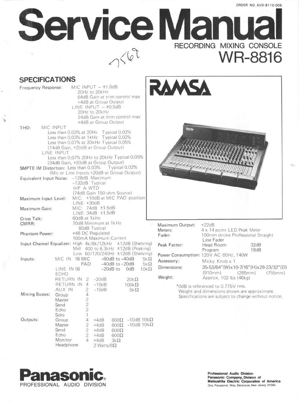
Panasonic wr 8816 ramsa service manual

This is the 46 pages manual for panasonic wr 8816 ramsa service manual.
Read or download the pdf for free. If you want to contribute, please mail your pdfs to info@audioservicemanuals.com.

Page: 1 / 46
left right
panasonic wr 8816 ramsa service manual

Extracted text from panasonic wr 8816 ramsa service manual (Ocr-read)


Page 2

LOCATION OF CONTROLS

INPUT MODULE

WU-8001

In addition to 16 microphone inputs, the input modules
on the WR-8816 can also accommodate 16 line inputs #
a total of 32 inputs - plus 16 direct line outputs. This
means that multiatrack recording or overdubbing may be
performed without time consuming changes in patch
connections. The additional Left, Right channel assign»
ment capability permits input signals to bypass the
Group modules for direct Zatrack mixdown or monitor
ing. Each module is equipped with its own equalizer,
echo, and volume controls for flexible adjustments at
the input stage,

1. Peak LED

The peak LED indicates that GdB of headroom remains
in the pre-amp section. By adjusting the input/trim
control as high as it can go before the LED flashes
during peaks, you can obtain the optimum S/N ratio,
while retaining low distortion. The LEDs indication
applies to prevEO, pre-fader signals.

2. Phase Switch

This switch allows instant phase reversal of the micro
phone connected at each input. If an out-of-phase
condition exists (a possibility if two microphones are
mixing the same instrument, or if the cables are
connected in reverse), this convenient switch can return
the mic to normal phase. This is an enormous timeesaver,
especially when compared to resoldering the mic cables
(required by some mixers to reverse the phase).

3. Input/Trim

To keep input signals below the clipping level of the
pre-amp, input sensitivity level can be set as high as
-60dB, in three increments of -20dB each. Since the
trim takes effect before the insertion jack, it allows ad-
justment to the optimum level for connection of ex-
ternal equipment.

4. Equalizer
These controls offer the engineer maximum flexibility in
tonal adjustment - a sophisticated 3-band variable fre»
quency equalizer section is included. The center knob
controls the level adjustment and includes a OdB center
detent. The outer knob adjusts the frequency.
These rotary pots provide the input signals with three
bands of E0 adjustment.

HIGH 4kHz,8kHz,12kHz i12dB

MID 400Hz#6.3kHz il2dB

LOW 60Hz, lZOHz, 24OHz il2dB

For the midrange control, a continuously variable rotary
knob permits precise frequency adjustment, covering
about one octave around the center frequency. The Low
and High EO settings are 3-position shelving-type con-
trols.

5. Equalizer ON Switch

Using this switch, you can turn the equalizer on or off
without resetting the level adjustment positions.

6. High Pass Filter Switch

In comparison with the lowest EQ setting (a maximum
attenuation of -12dB at 60Hz), this filter provides a
sharper -18dB/octave cutoff at 80HZ. This is useful for
eliminating low frequency vibrations (which may occur
when using hand held mics) or to provide greater
microphone isolation.