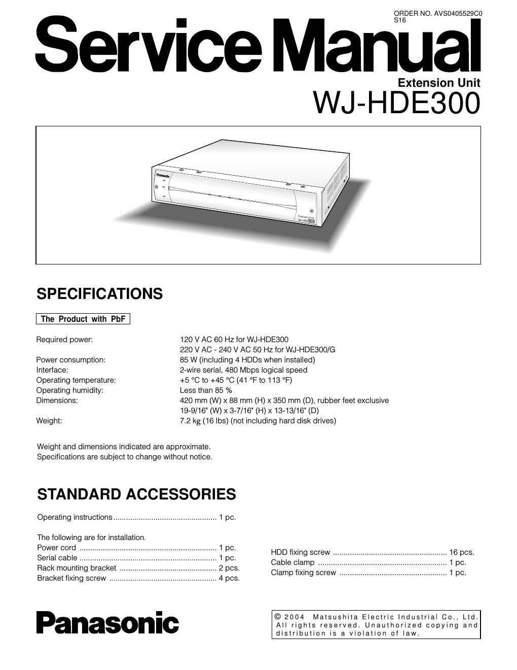
Panasonic wj hde 300 service manual

This is the 44 pages manual for panasonic wj hde 300 service manual.
Read or download the pdf for free. If you want to contribute, please mail your pdfs to info@audioservicemanuals.com.

Page: 1 / 44
left right
panasonic wj hde 300 service manual

Extracted text from panasonic wj hde 300 service manual (Ocr-read)


Page 1

ORDER NO. AVSO40552900

Service ManUaI

Extension Unit

WJ-HD :300

SPECIFICATIONS

Required power: 120 V AC 60 Hz for WJiHDESOO
220 V AC 7 240 V AC 50 Hz for WJeHDESOO/G

Power consumption: 85 W (including 4 HDDs when installed)

Interface: Zwire serial, 480 Mbps logical speed

Operating temperature: +5 °C to +45 °C (41 °F to 113 °F)

Operating humidity: Less than 85 %

Dimensions: 420 mm (W) x 88 mm (H) X 350 mm (D), rubber feet exclusive
1979/16 (W) X 37/16 (H) X 1343/16" (D)

Weight: 7.2 kg (16 lbs) (not including hard disk drives)

Weight and dimensions indicated are approximate.
Specifications are subject to change without notice.

STANDARD ACCESSORIES

Operating instructions ................................................. 1 pc.

The following are for installation.


Power cord ................................................................. 1 pc. HDD fixing screw _ .. 16 pcs.
Serial cable ................... 1 pc.
_ Cable clamp ..
Rack mounting bracket 2 pcs. .
_ _ Clamp fiXing screw ..
Bracket fiXing screw ................................................... 4 pcs.

- © 2004 Matsushita Electric Industrial 00., Ltd.
nasonlc All rights reserved. Unauthorized copying and

distribution is a violation of law.

Page 2

A WARNING

This service information is designed for experienced repair technicians only and is not designed for use by the
general public.

It does not contain warnings or cautions to advise non-technical individuals of potential dangers in attempting to
service a product.

Products powered by electricity should be serviced or repaired only by experienced professional technicians. Any
attempt to service or repair the product or products dealt with in this service information by anyone else could
result in serious injury or death.

This symbol warns the user that uninsulated voltage within

it_ CAUTION iii the unit may have sufficient magnitude to cause electric

RISK OF ELECTRIC SHOCK shock. Therefore, it is dangerous to make any kind of contact
_0 NOTOPEN with any inside part of this unit.

CAUTION:

TO REDUCE THE RISK OF ELECTRIC SHOCK.

DO NOT REMOVE COVEFl (OR BACK)- N0 USER This symbol alerts the user that important literature concerning
SERVICEABLE PARTS INSIDE. the operation and maintenance of this has been included.
REFER SERVICING TO QUALIFIED SERVICE Therefore, it should be read carefully in order to avoid
PERSONNEL. any problems.

IMPORTANT SAFETY NOTICE

There are special components used in this equipment which are important for safety. These parts are indicated
by the "A" mark on the schematic diagram and the replacement parts list. It is essential that these critical
parts should be replaced with manufacturer's specified parts to prevent X-radiation, shock, fire, or other hazards.
Do not modify the original design without permission of manufacture.

About Lead Free Solder (PbF)

Distribution of PbF PCB:
PCBs (manufactured) using lead free solder (PbF) will have a stamp on the PCB.

Caution:
I Lead free solder has a higher melting point than standard solder. Typically the melting points is 35 °C - 40 C
(95 °F - 104 °F) higher. Please use a soldering iron with temperature control and adjust it to 360 °C - 370 °C
(680 F - 698 °F). In case of using high temperature soldering iron, please be careful not to heat too long.
I Lead free solder will tend to splash when heated too high (600 °C / 1112 °F).
0 Lead free solder (Sn - 3.0Ag - 0.50u) or equivalents are recommended on repairing our lead free soldered PCB.