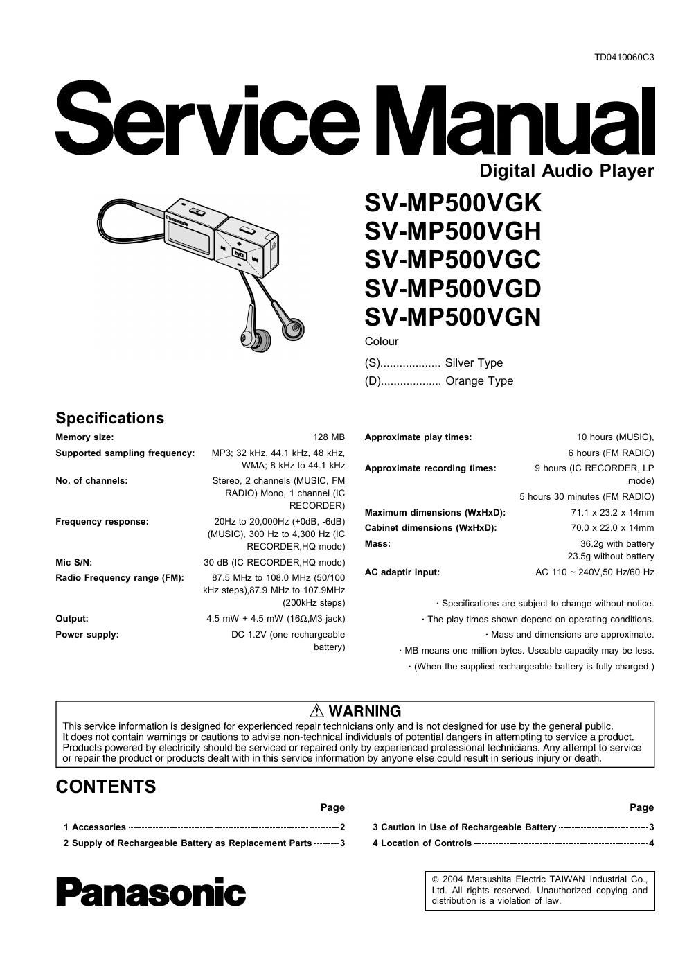
Panasonic sv mp 500 vgc service manual

This is the 36 pages manual for panasonic sv mp 500 vgc service manual.
Read or download the pdf for free. If you want to contribute, please mail your pdfs to info@audioservicemanuals.com.

Page: 1 / 36
left right
panasonic sv mp 500 vgc service manual

Extracted text from panasonic sv mp 500 vgc service manual (Ocr-read)


Page 1

TD0410060C3

Service Manual

Specflhafions

Memory size: 128 MB

MP3; 32 kHz, 44.1 kHz, 48 kHz,
WMA; 8 kHz to 44.1 kHz

Stereo, 2 channels (MUSIC, FM
RADIO) Mono, 1 channel (IC
RECORDER)

20HZ to 20,000HZ (+0dB, -GdB)
(MUSIC), 300 HZ to 4,300 HZ (IC
RECORDER,HQ mode)

30 dB (IC RECORDER,HQ mode)
87.5 MHZ to 108.0 MHZ (50/100
kHz steps),87.9 MHz to 107.9MH2
(200kHz steps)

4.5 mW + 4.5 mW (moms jack)
DC 1.2V (one rechargeable
battery)

Supported sampling frequency:

No. of channels:

Frequency response:

Mic SIN:
Radio Frequency range (FM):

Output:
Power supply:

Digital Audio Player

SV-MP500VGK
SV-MP500VGH
SV-MP500VGC
SV-MP500VGD
SV-MP500VGN

Colour
(8) ................... Silver Type
(D) ................... Orange Type

Approximate play times: 10 hours (MUSIC),
6 hours (FM RADIO)

9 hours (IC RECORDER, LP
mode)

5 hours 30 minutes (FM RADIO)
71.1x 23.2 x 14mm
70.0 x 22.0 x 14mm

36.29 with battery
23.59 without battery

AC 110 ~ 240V,50 Hz/60 HZ

Approximate recording times:

Maximum dimensions (WxHxD):
Cabinet dimensions (WxHxD):
Mass:

AC adaptir input:

- Specifications are subject to change without notice.

- The play times shown depend on operating conditions.

- Mass and dimensions are approximate.

- MB means one million bytes. Useable capacity may be less.
- (When the supplied rechargeable battery is fully charged.)

AWARNING

This service information is designed for experienced repair technicians only and is not designed for use by the general public.

It does not contain warnings or cautions to advise non-technical individuals of potential dangers in attempting to service a product.
Products powered by electricity should be serviced or repaired only by experienced professional technicians Any attempt to service
or repair the product or products dealt with in this service information by anyone else could result in serious injury or death.

CONTENTS

Page
1 Accessories ---------------------------------------------------------------------------- 2
2 Supply of Rechargeable Battery as Replacement Parts --------- 3

Panasonic

Page
3 Caution in Use of Rechargeable Battery ................................ 3
4 Location of Controls --------------------------------------------------------------- 4

© 2004 Matsushita Electric TAIWAN Industrial Co.,
Ltd. All rights reserved. Unauthorized copying and
distribution is a violation of law.

Page 2

SV-MPSUOVGK I SV-MPSDDVGH l SV-MPSOOVGC l SV-MPSUOVGD I SV-MPSDOVGN

5 Operation Checks and Component Replacement Procedures!»
5.1. Removal of the battery cover ------------------------------------------ 5

5.2. Removal of the front cabinet
5.3. Removal of the memory P.C.B.

5.4. Removal of the main P.C.B_ ...........................................
5.5. Removal of the battery terminaL .....................................
5.6. Removal of the LCD Ass I] ............................................

5.7. Removal of the LCD Piece ----------------------
5.8. Removal of the mode button and hold knob-
5.9. Removal of the USB fix piece and USB cover-

5.10. Removal of the REC button ............................................
5.11. Removal of the tuner P.C.B. and Mic ass [1 ..................

6 Service Position
7 Service Mode-

1 Accessories

- Stereo earphones

(LOBABOOOO187) ............................................................. 1pc.

- USB Cable

(K1 HA05AD0003) ............................................................. 1pc.

- Neck Strap

(RFATOOOB-Q) .................................................................. 1pc.

- CD-ROM Driver

(RFE0164) ........................................................................ 1pc.

©

- Adaptor
(NOJECDOOOOOt) ........................................................... [GK]t
(NOJECDOOOOOZ) ........................................................... [GD].
(NOJECDOOOOO3) ........................................................... [GC].
(NOJECDOOOOO4) ........................................................... [GH].

(NOJECDOOOOOS) ........................................................... [GN].

7.1. Checking Procedures for |C3 CZDBGL000001 ................ 9

7.2. Checking Procedures for Fonttable ............................... 10

8 The Method of Download of DFU Software- 11
9 Troubleshooting --------------------------------------- 15
10 Troubleshooting guide ---------------------------------------------------------- 15
11 Type Illustration of le, Transistors and Diodes .................. 15
12 Block Diagram ---------------------------------------------------------------------- 17

13 Schematic Diagram Notes ..............
14 Printed Circuit Board Diagram Notes-

15 Schematic Diagram _________________________
16 Printed Circuit Board Diagram ______________________________________________ 28
17 Cabinet Parts Location _________________________________________________________ 32
18 Packaging .................

19 Replacement Parts List

- Battery Ass'y

(ZBRP-BP65HE) tttttttttttttttttttttttttttttttttttttttttttttttttttttttttttttttt 1pc.
1 - X
I l
' Q '
l I
I |
' I
l I
l I
l I
l |
: y I
\ :
x _________________ g;

- Battery Case
(RFCT0005- H) ............................................................ 1 pct

%