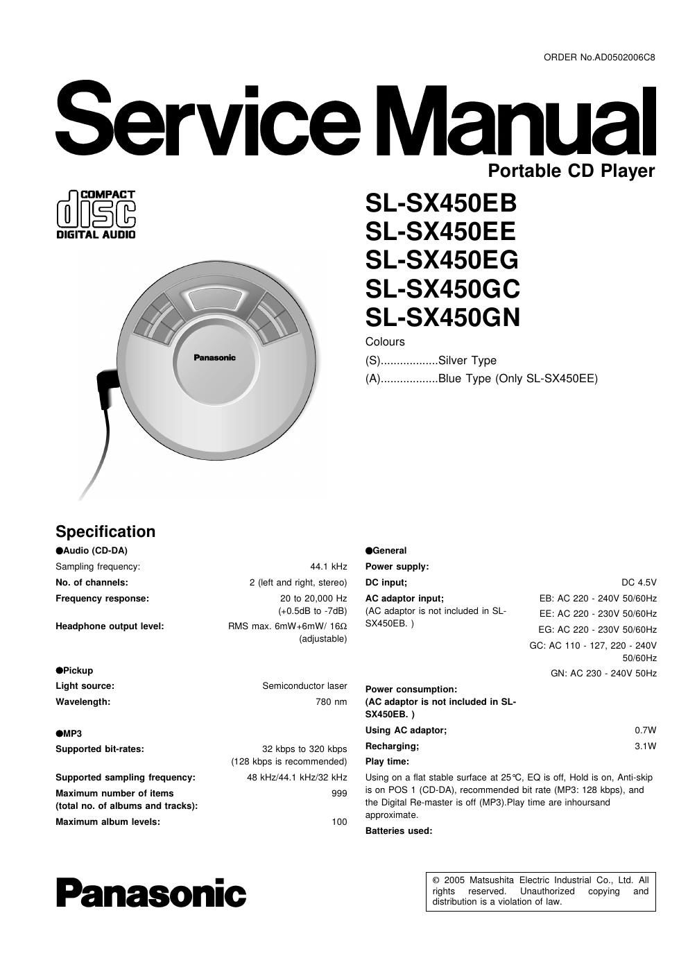
Panasonic sl sx 450 eg service manual

This is the 35 pages manual for panasonic sl sx 450 eg service manual.
Read or download the pdf for free. If you want to contribute, please mail your pdfs to info@audioservicemanuals.com.

Page: 1 / 35
left right
panasonic sl sx 450 eg service manual

Extracted text from panasonic sl sx 450 eg service manual (Ocr-read)


Page 2

SL-SX450EB / SL-SX450EE / SL-SX450EG l SL-5X450GC / SL-SXASDGN

2 optional alkaline batteries; MP3 disc....85h
CD-DA disc....50h
2 optional rechargeable batteries; MP3 disc .40h
CD-DA disc....23h
Recharging time: 4 to 5 hours

~ The play time may be less depending on the operating conditions.
~ Play time will be considerably reduced when playing CD-RW.

0°C-40°C

5°C-40C

135x23.8x135mm

202g (with batteries)

158g (without batteries)

Operational temperature range:
Rechargeable temperature range:
Dimensions (WxHxD):

Mass:

Note:
Specifications are subject to change without notice.
Mss and dimensions are approximate.

Note on CD-R and CD-RW:

This unit can play CD-R and CD-RW recorded with CD-DA or MP3.
Use an audio recording disc for CD-DA and finalize it when you
finish recording. The unit may not be able to play some discsduetothe
condition of the recording.

A process performed after recording that enables CD-R/CD-RW
players to play audio CD-Ft and CD-RW.

AWARNING

This service information is designed for experienced repair technicians only and is not designed for use by the general public.

It does not contain warnings or cautions to advise non-technical individuals of potential dangers in attempting to service a product.
Products powered by electricity should be serviced or repaired only by experienced professional technicians. Any attempt to service
or repair the product or products dealt with in this service information by anyone else could result in serious injury or death.

CONTENTS

1 Precaution of Laser Diode


2 Accessories
3 Handling Precau ons for Traverse Deck

3.1. Handling the traverse deck (optical pickup) ..................... 4

3.2. Caution when replacing traverse deck ---------

33- Grounding for electrostatic breakdown prevention ............ 4
4 Operation Checks and Component Replacement Proceduress

4.1. Checking for the PCB. ass D --------------------------------------- 6

4.2. Replacement for the CD lid unit ...................................... 8

43. Replacement for the LCD, button L, button R and multi
button SW unit ----------------------------------------------

4.4. Replacement for the spring holder and open spring -9
4.5. Replacement for the traverse motor ................... 10
4.6. Replacement for the optical pick-up .............................. 10
4.7. Replacement for the rest switch .................................... 12

5 Checking the Operation Problems on the Traverse Deck
(Optical Pickup)
6 Automatic Adjustment Results Display Function (Self-check

Function) ------------------------------------------------------------------------------- 14
6.1. How to display aUtomatic adjustment results ----------------- 14

1 Precaution of Laser Diode

CAUTION:

6.2. Display of automatic adjustment results (self-check
function)-

7 Display of Self-Diagnostic Function
8 Type Illustration of Ions, Transistors and Diodes ---------------- 15
9 Schematic Diagram Notes ---------------------------------------------------- 16
17

10 Schematic Diagram ............
11 Printed Circuit Board and Wiring Connection Diagram

12 Block Diagram ------------------------------------------------------------

13 Terminal Function of ICS -------------------------------------------- 25
13.1. |C101(AN22003A-NF): Servo Amplifier -------------------------- 25
13.2. |C301(CZBBGE000792): System Control / LCD Drive ----25
13.3. |0501(MN662793SCM):Servo Processor/ Digital Signal

Processor/ Digital Filter 8. WA Converter ....................... 25
14 Replacement Parts List ......................................................... 27
15 Cabinet Parts Location ......................................................... 30

16 Traverse Parts Location
17 Packaging
17.1. SL-SX450EB-
17.2. SL-SX450EE/EG/GN .................................................... 33
17.3. SL-SX450GC ............................................................... 34

This unit utilizes a class 1 laser. Invisible laser radiation is emitted from the pickup lens when the unit is turned on:

1.Do not look directly into the pickup lens.
2. Do not use optical instruments to look at the pickup lens.

3. Do not adjust the preset variable resistor on the optical pickup.

4. Do not disassemble the optical pickup unit.

5. If the optical pickup is replaced, use the manufactures specified replacement pickup only.

6. Use of control or adjustments or performance of procedures other than those specified herin may result in hazardous