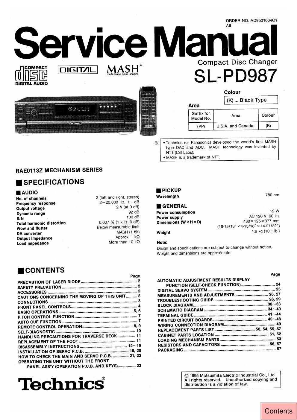
Panasonic sl pd 987 service manual

This is the 54 pages manual for panasonic sl pd 987 service manual.
Read or download the pdf for free. If you want to contribute, please mail your pdfs to info@audioservicemanuals.com.

Page: 1 / 54
left right
panasonic sl pd 987 service manual

Extracted text from panasonic sl pd 987 service manual (Ocr-read)


Page 1

ORDER NO. A0950100401

Service Manual

@COMPACT

m MASH

multl- stage noise shaping

DIGITAL AUDIO

"was:

RAEO1132 MECHANISM SERIES

ISPECIFICATIONS
IAUDIO

No. ot channels
Frequency response

2 (left and right, stereo)
2-20.000 Hz, :1 dB

Output voltage 2 V (at 0 dB)
Dynamic range 92 dB
SIN 100 dB

Total harmonic distortion
Wow and Ilutter

DA converter

Output impedance

Load Impedance

0.007 % (1 kHz, 0 dB)
Below measurable limit
MASH (1 bit)

Approx. 1 k0

More than 10 k0

I CONTENTS

PRECAUTION OF LASER DIODE
SAFETY PRECAUTION .
ACCESSORIES ...........
CAUTIONS CONCERNING THE MOVING OF THIS UNIT.
CONNECTIONS .................
FRONT PANEL CONTROLS
BASIC OPERATIONS ........
PITCH CONTROL FUNCTION.
AUTO CUE FUNCTION ........
REMOTE CONTROL OPERATION.
SELF-DIAGNOSTIC .....................
HANDLING PRECAUTIONS FOR TRAVERSE DECK.
REPLACEMENT OF THE FOOT
DISASSEMBLY INSTRUCTIONS 12~19
INSTALLATION OF SERVO P.C.B
HOW TO CHECK THE MAIN AND SERVO P. C. B
OPERATING THE UNIT WITHOUT THE FRONT
PANEL ASSY (OPERATION P. C. B. AND KEYS) ................ 23

Technic§

Pag


uuo-pwunnno

>Z< -Technics (or Panasonic) developed the worlds first MASH

Compact Disc Changer

SL- PD987

Colour
(K) Black Type

Area
Suffix for
Model No. Area Colour
(PP) USA. and Canada. (K)

type DAC and ADC, MASH technology was invented by
NTT (LSI Labs).
0 MASH is a trademark of NTT.

I PICKUP

Wavelength 780 nm
I GEN ERAL

Power consumption 12 W
Power supply AC 120 V, 60 Hz

430 X 125 X 377 mm
(16»15/16" x4-15I16 X 14-27132")
Weight 4.6 kg (10.1 lb.)

Dimensions (W x H x D)

Note:

Disign and specifications are subject to change without notice.
Weight and dimensions are approximate.

AUTOMATIC ADJUSTMENT RESULTS DISPLAY

FUNCTION (SELF-CHECK FUNCTION) ..... 24
DIGITAL SERVO SYSTEM ...................
MEASUREMENTS AND ADJUSTMENT
TROUBLESHOOTING GUIDE
BLOCK DIAGRAM....
SCHEMATIC DIAGRA
TERMINAL GUIDE .......
PRINTED CIRCUIT BOARDS
WIRING CONNECTION DIAGRAM
REPLACEMENT PARTS LIST...
CABINET PARTS LOCATION
LOADING MECHANISM PART
RESISTORS AND CAPACITORS ........
PACKAGING 57

© 1995 Matsushita Electric Industrial Co., Ltd.
All rights reserved. Unauthorized copying and

distribution is a violation of law.
Contents

Page 2

SL-PD987

This

does not contain warnings or cautions to advise non-technical individuals of potential dangers in attempting to service a product.
Products powered by electricity should be serviced or repaired only by experienced professional technicians. Any attempt to service
or repair the product or products dealt with In this service Information by anyone else could result In serious injury or death.

A WARNING
service information is designed for experienced repair technicians only and is not designed for use by the general public. It

IPRECAUTION OF LASER DIODE

CAUTION: This unit utilizes a class 1 laser. Invisible laser radiation is emitted from the optical pickup lens when

the unit is turned on:

1. Do not look directly into the pickup lens.

Do not use optical instruments to look at the pickup lens.

Do not adjust the preset variable resistor on the optical pickup.

Do not disassemble the optical pickup unit.

If the optical pickup is replaced, use the manufactures specified replacement pickup only.

Use of control or adjustments or performance of procedures other than those specified herin may
result in hazardous radiation exposure.

eweww

.SAFETY PRECAUTION (This safety precaution" is applied only in U.S.A.)

f-PPPr

O

1.
2.
3.

Before servicing, unplug the power cord to prevent an electric shock.

When replacing parts, use only manufacturer's recommended components for safety.

Check the condition of the power cord. Replace If wear or damage is evident.

After servicing, be sure to restore the lead dress, Insulation barriers, Insulation papers, shields, etc.

Before returning the serviced equipment to the customer, be sure to make the following insulation resistance
test to prevent the customer from being exposed to a shock hazard.

INSULATION RESISTANCE TEST

Unplug the power cord and short the two prongs of the plug with a jumper wire.

Turn on the power switch.

Measure the resistance value with ohmmeter between the jumpered AC plug and each exposed metal cabinet
part, such as screwheads antenna, control shafts, handle brackets, etc. Equipment with antenna terminals
should read between GM!) and 5.2M!) to all exposed parts. (Fig. A) Equipment without antenna terminals
should read approximately infinity to all exposed parts. (Fig. B)

Note: Some exposed parts may be isolated from the chassis by design. These will read infinity.

Antenna
Ierminal\

Exposed Exposed 9
metal part metal part
ohmmeter ohmmeter
(Flg- A) (Fig. B)
Resistance=3MQ-5.ZMQ Resistance=Approx co
4. If the measurement is outside the specified limits, there is a possibilty of a shock hazard. The equipment
should be repaired and rechecked before it is returned to the customer.

AC power supply cord. . . 1 pc. Stereo connection Remote control Batteries for remote
(SJA172) Cable .................. 1 pc. transmitter ............. 1 pc. control transmitter ..... 2 pcs.

(SJP2249-3) (RAK~SL122WH) (UM-4, AAA", R03)

Note: These are available on
sale route.