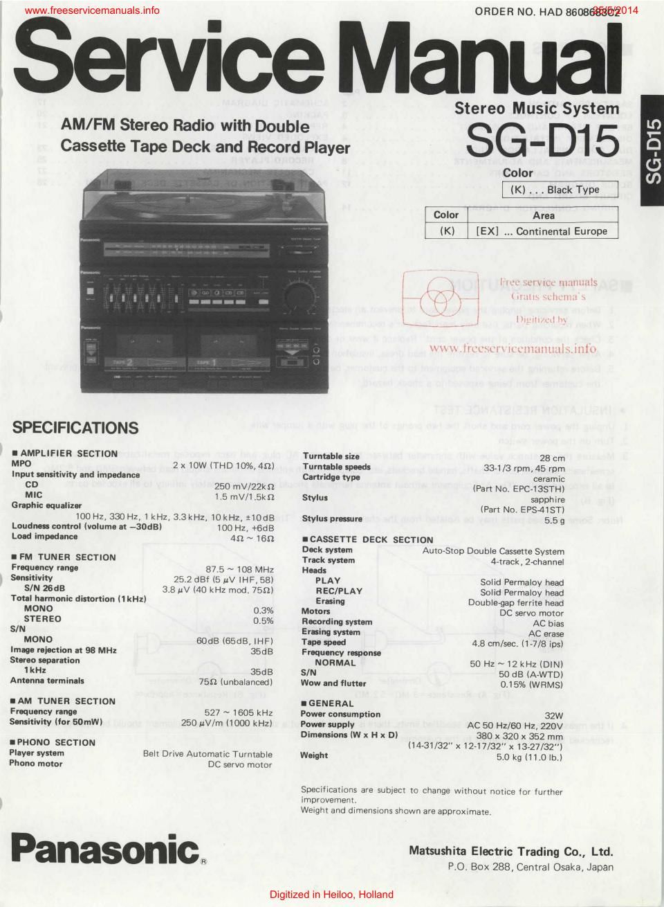
Panasonic sg d15 service manual

This is the 20 pages manual for panasonic sg d15 service manual.
Read or download the pdf for free. If you want to contribute, please mail your pdfs to info@audioservicemanuals.com.

Page: 1 / 20
left right
panasonic sg d15 service manual

Extracted text from panasonic sg d15 service manual (Ocr-read)


Page 1

www.freeservicemanuals.info O R DE R N0. HAD BBDBSWUZOM

Service Manual

Stereo Music System

SG-D15

¥golor Area
(KI [EX] Continental Europe

AM/FM Stereo Radio with Double
Cassette Tape Deck and Record Player

SPECIFICATIONS
l AMPLIFIER SECTION Turntable site 28 cm
MPO 2 x 10W (THD 10%, 49) Turntable speed: 331 /3 rpm, 45 rpm
Input sensitivity and impedance Cartridge type ceramic
CD 250 mV/ZZkQ (Part No. EPC-13STH)
MIC 1.5 mV/1.5kn Stylus sapphire
Graphic eeualizar (Part No. EPS~41$TI
100 Hz, 330H2, 1 kHz, 3.3 kHz, iOkHzl :10dB Styluspreeeure 5.59

SG-D15

Loudness control (volume at -30dBI 100 Hz, +6dB
Load impedance 4n ~ 169 ICASSETTE DECK SECTION
Deck system Auto-Stop Double Cassette System
I FM TUNER SECTION Track system 4rtrack, Zahannel
Frequency range 87.5 ~ 108 MHz Heads
Sensitivity 25 2 [181 (5 1.4V IHF, 58) PLAV Solid Permalov head
SIN ZEdB 3.8 1.1V [40 kHz mod. 75.12) REC/PLAY Solid Permaloy head
Total harmonic distortion (1 kHz) Erasing Doublegap ferrite head
MONO 0.3% Motors DC servo motor
STEREO 0.5% Recording system AC bias
S/N Erling system AC erase
MONO 60GB lGSdB. lHF) Tape speed 4.8 cm/sec. (1-7/8 ipsl
Image rejection at 98 MHz 35dB Frequency response
Stereo separation NORMAL 50 HZ ~ 12 kHz (DIN)
IkHz 35dB SIN 50 dB (A-WTDI
Antenna terminals 750 (unbalancedl Wow and flutter 0.15% (WRMS)
IAM TUNER SECTION IGENERAL
Frequency range 527 ~ 1505 kHz Power consumption 32W

Sensitivity (for EOmWI

IPHONO SECTION
Player system
Phone motor

250 uV/m (1000 kHz) Power supply

Dimensions (W x H x D)

Belt Drive Automatic Turntable Weight
DC servo motor

AC 50 Hz/GO Hz, 220V
380 x 320 x 352 mm

I14-31/32"x12-17/32" x13-27/32")

5.0 kg 111.0 lb.)

Specifications are SUDIECI to change without notice for further

improvement,

Weight and dimensions shown are approximate,

Panasonic.

Digitized in Heiloo, Holland

Matsushita Electric Trading Co., Ltd.
PO. Box 288, Central Osaka, Japan

Page 2

www.freeservicemanuals.info

ICONTENTS
Page
SAFETY PRECAUTION ......................... 2
LOCATION OF CONTROLS ...................... 3
BEFORE REPAIR AND ADJUSTMENT . . . 4
DISASSEMBLV INSTRUCTIONS ....... 4
DIAL CORD INSTALLATION GUIDE . . . . B
MEASUREMENTS AND ADJUSTMENTS . . B
RESISTORS AND CAPACITORS ....... . . . . II
BLOCK DIAGRAM ..................... . 12

CIRCUIT BOARD AND
WIRING CONNECTION DIAGRAM ................ 14

ISAFETY PRECAUTION

UIJIUNF

the customer from being exposed to a shock hazard.

O INSULATION RESISTANCE TEST

25/5/2014

Pm
SCHEMATIC DIAGRAM ......................... i7
PACKING .............. . . . . . . . . .
REPLACEMENT PARTS LIST ..................... 21
EXPLODED VIEWS
CABINET AND CHASSIS ...................... 23
REcORD PLAYER ......................... 25
CASSETTE MECHANISM ...................... 27
PARTS LOCATION or CASSETTE DECK MECANISM ..... zs

. Before servicing, unplug the power cord to prevent an electric shock.

. When replacing parts. use only manufacturers recommended components lor salety.

. Check the condition of the power cord. Replace if wear or damage is evident.

. After servicing, be sure to restore the lead dress, insulation barriers, insulation papers, shields, etc.

. Before returning the serviced equipment to the customer, be sure to make the following insulation resistance test to prevent

1. Unplug the power cord and short the two prongs of the plug With a jumper wire.

2. Turn on the power switch.

3. Measure the resistance value WIIII ohmmeter between the jumpered AC plug and each exposed metal cabinet part. such as
screwheads antenna, cotrol shafts, handle bmckets, etc. Equipment with antenna terminals should read between 3Mn and 5.2Mn
to all exposed parts. (Fig. A) Equipment Without antenna terminals should read apmeImately infinity to all exposed parts.

(Fig. B)

Note: Some exposed parts may be isolated from the chassis by design. These will read infinity

Antenna \
terminal

Exposed /
metal
part

Ohmmeter
(Fig. A) Resistance=3 MD-5.2 Mn

Exposed ~m
metal
part

Ohmmeter
(FIE. B) Resistance=Approxco

4. It the measurement is outside the specified limits, there is a possibility of a shock hazard. The equipment should be repaired and

rechecked before it is returned to the customer.

Digitized in Heilefi,-Holland