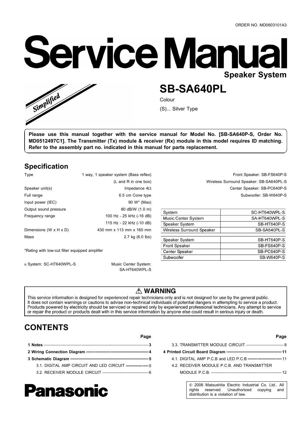
Panasonic sb sa 640 pl service manual

This is the 20 pages manual for panasonic sb sa 640 pl service manual.
Read or download the pdf for free. If you want to contribute, please mail your pdfs to info@audioservicemanuals.com.

Page: 1 / 20
left right
panasonic sb sa 640 pl service manual

Extracted text from panasonic sb sa 640 pl service manual (Ocr-read)


Page 1

ORDER NO. MD0603101A3

Manual

Speaker System
SB-SA640PL

Colour

(8)... Silver Type

Please use this manual together with the service manual for Model No. [SB-SA64OP-S, Order No.
MD0512497C1]. The Transmitter (Tx) module & receiver (Rx) module in this model requires ID matching.
Refer to the assembly part no. indicated in this manual for parts replacement.

Spedficafion
Type 1 way, 1 speaker system (Bass reflex) Front Speaker: SB-FS640P-S
(L and R in one box) Wireless Surround Speaker: SB-SA64OPL-S
Speaker unit(s) Impedance 40 Center Speaker: SB-PCS4OP-S
Full range 6.5 cm Cone type Subwoofer: SB-W640P-S
Input power (IEC) 90 W (Max)
Output sound pressure 80 dB/W (1.0 m)
Frequency range too Hz - 25 kHz (45 dB) Wei SCHTMOWPL'S
MUSIC Center System SA»HT640WPL-S
115 Hz - 22 kHz (40 dB) Speaker System SB-HT640P-S
Dimensions (W x H x D) 430 mm x 113 mm x 160 mm Wireless Surround Speaker SB-SA640PL-S
Mass 2'7 kg (60 lbs) Speaker System SB»HT640P-S
Front Speaker SB-FSB40PeS
Rating with low-cut filter equipped amplifer Center Speaker 33_p0540p_3
Subwoofer SB-W64OP-S
n System: SC-HT640WPL-S Music Center System:

SA-HT64OWPL-S

A WARNING

This service information is designed for experienced repair technicians only and is not designed for use by the general public.

It does not contain warnings or cautions to advise non-technical individuals of potential dangers in attempting to service a product.
Products powered by electricity should be serviced or repaired only by experienced professional technicians. Any attempt to service
or repair the product or products dealt with in this service information by anyone else could result in serious injury or death.

CONTENTS

Page Page

1 Notes -------------------------------------------------------------------------------------- 3 3.3. TRANSMITTER MODULE CIRCUIT ------------------------------- 3

2 Wiring Connection Diagram --------------------------------------------------- 4 4 Printed Circuit Board Diagram ---------------------------------------------- 11

3 Schematic Diagram ----------------------------------------------------------------- 5 4.1. DIGITAL AMP PCB and LED p_c_B ---------------------------- 11
3.1. DIGITAL AMP CIRCUIT AND LED CIRCUIT ------------------- 5 4.2. RECEIVER MODULE P.C.B. AND TRANSMITTER

3.2. RECEIVER MODULE CIRCUIT -------------------------------------- 6 MODULE P.C.B. .......................................................... 12

© 2006 Matsushita Electric Industrial Co. Ltd.. All

I
rights reserved. Unauthorized copying and
distribution is a violation of law.