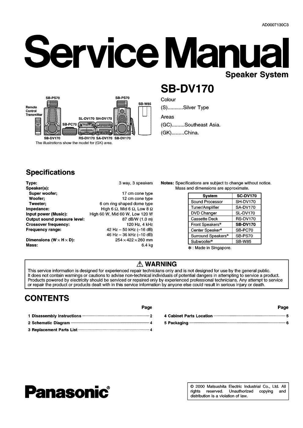
Panasonic sb dv 170 service manual

This is the 6 pages manual for panasonic sb dv 170 service manual.
Read or download the pdf for free. If you want to contribute, please mail your pdfs to info@audioservicemanuals.com.

Page: 1 / 6
left right
panasonic sb dv 170 service manual

Extracted text from panasonic sb dv 170 service manual (Ocr-read)


Page 1

ADOOO71 30C3

Service Manual

SB-DVt 70

RS-DVt 70 SA-OV1ID SB-DV1 70

SB>W85

The illustrations show the model for (GK) area.

Speaker System

SB-DV17O

Colour
(S) ........... Silver Type

Specflmafions
Type: 3 way. 3 speakers Notes: Specifications are subject to change without notice.
Speaker(s): Mass and dimensions are approximate.

Super woofer; 17 cm cone type System sc-Dv17o

Woofer; 12 cm cone type

Tweeter; 6 cm ring shaped dome type Sound Processor SH'DW 70
Impedance: High 6 9, Mid 6 9, Low a n Tuner/Ampl'fler SADV170
Input power (Music): High so w, Mid 60 w, Low 120 w DVD Changer SL-DV170
Output sound pressure level: 87 (BM (1.0 m) Cassette Deck FIS-DV170
Crossover frequency: 120 Hz. 4 kHz Front Speakers SB-DV17O
Frequency range: 42 Hz - 50 kHz (-16 dB) Center Speaker SB-PC70

48 HZ " 35 kHZ (-10 05) Surround Speakers SB-PS7O
Dimensions (W x H x D): 254 x422 x 260 mm Subwoofer SB-W85
M883: 6'4 kg *: Made in Singapore.
A WARNING

This service information is designed for experienced repair technicians only and is not designed for use by the general public.

It does not contain warnings or cautions to advise non-technical individuals of potential dangers in attempting to service a product.
Products powered by electricity should be serviced or repaired only by experienced prolessional technicians. Any attempt to service
or repair the product or products dealt with in this service information by anyone else could result in serious injury or death.

CONTENTS

1 Disassembly Instructions
2 Schematic Diagram --------

3 Replacement Parts List --------

4

__________________________________________________ 4

Panasonic®

4 Cabinet Parts Location
5 PaCKaging .................

© 2000 Matsushita Electric Industrial 00., Ltd. All
rights reserved. Unauthorized copying and
distribution is a violation of law.

Page 2

1 Disassemblylnstructions

1.1. Removal of the speaker (Super
woofer)

(Step 1)
Remove the speaker net ass'y.

Step 4)
emove the woofer ring assy.

(Step 5)
0

(Step 6) ? . 0
Remove the front f ?
panel ass'y.


(Step 2)
emove the 4
net catch gums.

(Step 8)
Lift up the speaker (Super woofer).

I Removal of the net catch gum

Plus screwdriver (3)
(1); 2) )

Net catch gum


1. Insert the plus screwdriver or similar tool into net catch
gum, push in slightly in the direction of arrow (1) to
avoid scratching, the cabinet ass'y and lift in the
direction of arrow (2).

2. After lifting the net catch gum, grasp it with your finger
and remove in the direction of arrow (3).