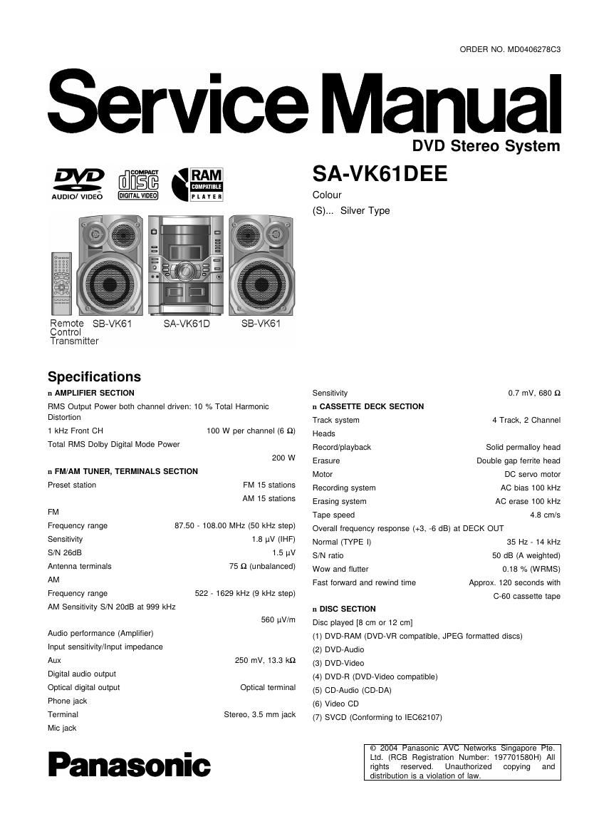
Panasonic sa vk61dee

This is the 156 pages manual for panasonic sa vk61dee.
Read or download the pdf for free. If you want to contribute, please mail your pdfs to info@audioservicemanuals.com.

Page: 1 / 156
left right
panasonic sa vk61dee

Extracted text from panasonic sa vk61dee (Ocr-read)


Page 2

SA-VK61 DEE

(8) CD-R/CD-RW (CD-DA, Video CD, SVCD, MP3, WMA, JPEG
formatted disc)

(9) MP3/WMA
~ Compatible compression rate:
MP3: between 32 kbps and 320 kbps
WMA: between 48 kbps and 192 kbps
(10) JPEG
~ Exif Ver 2.1 JPEG Baseline files
(11) HighMAT Level 2 (Audio and Image)
Sampling frequency

CD 44.1 kHz
MP3 32 kHz, 44.1 kHz, 48 kHz
DVD-Video 48 kHz, 96 kHz
DVD-Audio 44.1 kHz - 192 kHz
Decoding 16/20/24 bit linear

Wow and flutter
Less than possible measurement data
Digital filter 8 is

D/A converter Delta sigma DAC

Pick up

Wavelength

CD 780 nm
DVD 658 nm

Beam Source Semiconductor Laser
Audio output (Disc)

Number of channels 2 ch (stereo)
Audio performance (measured at LINE OUT terminal)

Frequency response
CD-Audio

n VIDEO SECTION

Video system

20 HZ - 20 kHZ (+1, -2dB)

PAL625/50, PAL525/60, NTSC

Composite video output
Output level 1 Vp-p (75 9)
Terminal Pin jack (1 system)
S-video output
Y output level 1 Vp-p (75 9)

0.3 Vp-p (75 :2) (PAL)
0.286 Vp-p (75 9) (NTSC)

8 terminal (1 system)

C output level

Terminal

Component video output
Y output level 1 Vp-p (75 $2)
0.7 Vp-p (75 :2)

0.7 Vp-p (75 9)

PB output level
PR output level
Terminal

Pin jack (Y: green, PB: blue, PR: red) (1 system)
11 GENERAL

Power supply AC 230V-240V, 50Hz

Power consumption 138 W
Power consumption in standby mode:

0.9 W
Dimensions (WxHxD) 250 x 330 X 358 mm
Mass 9.1 kg
n SYSTEM

SC-VK61D(EE) Music Center: SA-VK61D (EE)
Speaker: SB-VK61 (GO)
Notes:

1.Specifications are subject to change without notice. Mass and
dimensions are approximate.

2.Total harmonic distortion is measured by the digital spectrum
analyzer.

A WARNING

This service information is designed for experienced repair technicians only and is not designed for use by the general public.

It does not contain warnings or cautions to advise non-technical individuals of potential dangers in attempting to service a product.
Products powered by electricity should be serviced or repaired only by experienced professional technicians. Any attempt to service
or repair the product or products dealt with in this service information by anyone else could result in serious injury or death.

CONTENTS

Page
1 Before Repair and Adjustment ----------------------------------------------- 3
2 Protection Circuitry ----------------------------------------------------------------- 3
3 Safety Precautions ------------------------------------------------------------------ 4
3.1. General Guidelines -- --------------------------------------------------- 4

4 Prevention oi Electro Static Discharge (ESD) to
Electrostatically Sensitive (ES) Devices --------------------------------- 4
5 Handling the Lead-tree Solder ------------------------------------------------ 6
5.1. About lead free solder (PbF) ------------------------------------------ 6

6 Cautions to be taken when handling Optical Pickup

6.1. Handling Optical Pickup ---------------------------------

62- Replacing Precautions for Optical Pickup Unit ................. e
6.3. Grounding for Preventing Electrostatic Destruction ---------- 6
7 Precaution of Laser Diode ...................................................... 3
8 Accessories ............................................................................ 9

Page

9 Operation Procedures ........................................................... 10
10 Disc information ................................................................... 12
11 About HighMAT ..................................................................... 14
11.1. What is HighMAT?-- 14

11.2. Why use HighMAT? 14
11.3. The advantages of using HighMAT ------------------------------ 14
11.4. Outline of the HighMAT standard .................................. 15
12 Procedure for repairing the set ............................................ 17

12.1. Distinguish the trouble cause -- 18

12.2. Diagnosis of Optical Pick-up Unit 20
13 Optical Pickup Sell-Diagnosis and Replacement Procedure-22
13.1. Self-diagnosis -------------------------------------------------------------- 22

13.2. Cautions to Be Taken During Replacement of Optical
Pickup and Spindle Motor --------------------------------------------- 23