Panasonic sa ch84m

This is the 18 pages manual for panasonic sa ch84m.
Read or download the pdf for free. If you want to contribute, please mail your pdfs to info@audioservicemanuals.com.

Page: 1 / 18
left right
panasonic sa ch84m

Extracted text from panasonic sa ch84m (Ocr-read)


Page 1

SA-CH84M I

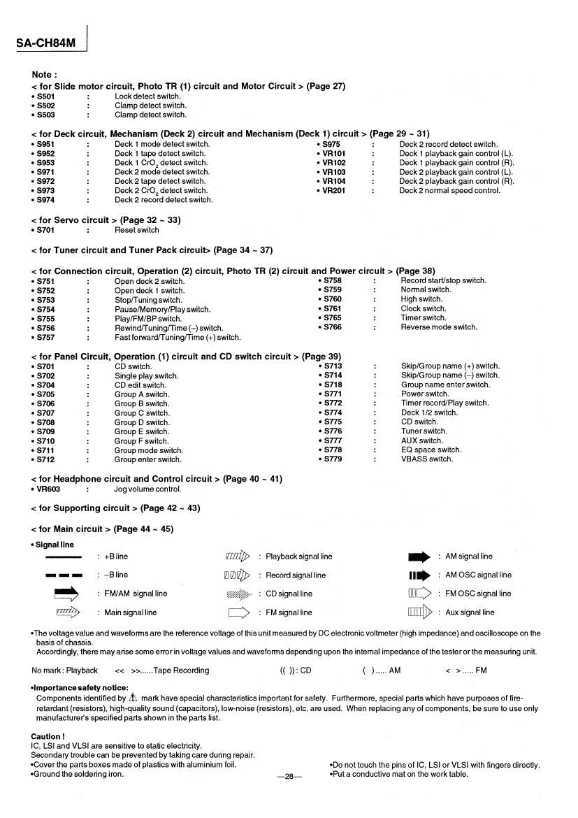
Note :

< for Slide motor circuit, Photo TR (1) circuit and Motor Circuit > (Page 27)

0 $501 : Lock detect switch,

0 $502 : Clamp detect switch.

. 5503 : Clamp detect switch.

< for Deck circuit, Mechanism (Deck 2) circuit and Mechanism (Deck 1) circuit > (Page 29~ 31)

. $951 Deck 1 mode detect switch. . $975 : Deck 2 record detect switch.

0 $952 : Deck 1 tape detect switch. - VR101 : Deck 1 playback gain control (L).
0 $953 : Deck 1 CrOZ detect switch. 0 VR102 : Deck 1 playback gain control (R).
- $971 : Deck 2 mode detect switch. . V8103 : Deck 2 playback gain control (L).
o 8972 : Deck 2 tape detect switch. - VR104 : Deck 2 playback gain control (R).
o 8973 : Deck 2 CrO2 detect switch. 0 VR201 : Deck 2 normal speed control.

. $974 : Deck 2 record detect switch.

< for Servo circuit > (Page 32 ~ 33)
- S701 : Reset switch

< tor Tuner circuit and Tuner Pack circuit> (Page 34 ~ 37)

< tor Connection circuit, Operation (2) circuit, Photo TR (2) circuit and Power circuit > (Page 38)

0 S751 : Open deck 2 switch. 0 5758 Record start/stop switch.

0 $752 : Open deck 1 switch ' S759 : Normal switch.

0 S753 : Stop/Tuning switch. 0 S760 : High switch.

0 S754 : Pause/Memory/Play switch. 0 $761 : Clock switch.

- S755 : Play/FM/BP switch. 0 S765 : Timerswitch.

0 S756 : Rewind/Tuning/Time (-) switch. 0 S766 : Reverse mode switch.

0 S757 : Fast forward/Tuning/Time (+) switch.

< for Panel Circuit, Operation (1) circuit and CD switch circuit > (Page 39)

0 S701 : CD switch - S713 : Skip/Group name (+) switch.
. S702 : Single play switch, - S714 : Skip/G roup name (~) switch.
- S704 : CD edit switch. 0 S718 : Group name enterswitch,

- S705 : Group A switch. 0 $771 : Power switch.

- S706 : Group B switch. 0 S772 : Timerrecord/Play switch.

- S707 : Group C switch. - $774 : Deck 1/2 switch.

0 $708 : Group D switch. 0 S775 : CD switch.

0 S709 : Group E switch. 0 S776 : Tunerswitch.

0 S710 : Group F switch. 0 $777 : AUX switch.

0 S711 : Group mode switch. - S773 : EQ space switch,

0 S712 : Group enter switch. 0 S779 : VBASS switch.

< for Headphone circuit and Control circuit > (Page 40 ~ 41)
- VR603 : Jog volume control.

< for Supporting circuit > (Page 42 ~ 43)

< for Main circuit > (Page 44 ~ 45)

°$ignalline
.- : +Bline : Playbacksignal line : AMsignalline
- : -B|ine : Recordsignalline fl. : AMOSCsignalline
a : FM/AM signal line ; CDsignalIine BBQ : FM OSCsignal line

E9 : Mainsignalline E:> : FMsignal line [[HID} : Auxsignal line

-The voltage value and waveforms are the reference voltage of this unit measured by DC electronic voltmeter(high impedance) and oscilloscope on the
basis of chassis,
Accordingly, there may arise some error in voltage values and waveforms depending upon the internal impedance of the tester or the measuring unit.

Nomark2PIayback << >>......Tape Recording (( )):CD ( ).....AM < >.....FM

olmportance safety notice:
Components identified by 1?: mark have special characteristics important for safety. Furthermore, special parts which have purposes of fire-
retaidant (resistors). high-quality sound (capacitors). low-noise (resistors), etc. are used. When replacing any of components, be sure to use only
manufacturers specified parts shown in the parts list.

Caution !

lC, LSI and VLSI are sensitive to static electricity.

Secondary trouble can be prevented by taking care during repair.

OCover the parts boxes made of plastics with aluminium foil. -Do not touch the pins of IC, LSl or VLSI with fingers directly,
oGround the soldering iron. -28- «Put a conductive mat on the work table.