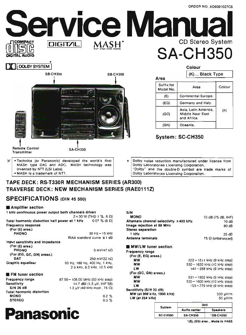
Panasonic sa ch350

This is the 60 pages manual for panasonic sa ch350.
Read or download the pdf for free. If you want to contribute, please mail your pdfs to info@audioservicemanuals.com.

Page: 1 / 60
left right
panasonic sa ch350

Extracted text from panasonic sa ch350 (Ocr-read)


Page 2

SA-CH350

I Cassene deck section
Track system
Heads
DECK 1 (playback)
DECK 2 (recordlplayback)
(erasure)
Molar
Recording syslem
Erase syslem
Tape speed
Frequency response
NORMAL
CrO,
METAL
SIN (Cro, type Iape)
Dolby NR all
Dolby NR on
Wow and Muller

4 lack. 2 channel

Permalloy head
Permalloy head

Double gap ielrlte head
DC servo moiol

AC buas,100 kHz

AC erase

4.8 crnfsec

4o Hz-M kHz (+3. -6 4a Hz-M kHz(+3. -5dB)
40Hz-15kHz(+3. -BdB)

52 dB (A-WTD)
Bl dB (0cm)
0.1 % (WRMS)

FasI lumen! and rewlnd lime
Approx. 110 seconds wilh 0-60 casseile laps

I Compacl disc player seclion

5m 95 dB Flllel (JIS A)
DIgiIaI filter 8 fs
MASH (I bit DAC)

DIA converlel

'CONTENTS

BEFORE USE"
PRECAUTION O LASER DIODE
ACCESSORIES ..........................
STACKING THE COMPONENTS.
CONNECTION-5..
LOCATION OF CONTROLS AND COMPONENT
REMOTE CONTROL UNIT CONTROLS AND FUNCTION
HANDLING PRECAUTIONS FOR TRAVERSE DECK.
DISASSEMBLY INSTRUCTION
PROTECTION CIRCUITRY .....
BEFORE REPAIR AND ADJUSTMENT.
MEASUREMENTS AND ADJUSTMENTS.
DIGITAL SERVO SYSTEML
TROUBLESHOOTING GUIDE


IBEFORE USE

(For (60) urea.)

Be sure to GISCDUHBCI the mains cord belore adjusting lire vollage
seTeclor,

Use a minus (-J screwdriver IO sel lhe vollage seleclor (on lhe rear
panel) lo lhe voltage selling for the area m which ihe uniI will be
used.

I General
Power consumption 180 w
Power supply
(For (ON) area.)
(For (E, E6) areas.)

AC SOIBO Hz. 230-240 V
AC 50/50 HZ. 230 V

(For (GO) area.) AC BINGO HZ. l10l127f2201240 V
Dimensions (WXHfl D) 215x329x335 mm
Welth 7.6 kg
I REMOTE CONTROL TRANSMITTER
Control key: 40 keys
Dimensions (W): H x D) 69.6 x266 x174 7 mm

Welght (wllhout bafleries) 106 9
Power source Two "AAA (R03iUM-4)

Noles:

1. Soeciiicallons are subject to change wilhoul nolice.
Welgnl and drmensrons are approximale.

2. Tolal harmonic dislorllon is measured by the dlgllal specllum
analyzer.

Page
BLOCK DIAGRAM .................................................................. 36~42
TERMINAL GUIDE OF ICS, TRANSISTORS AND DIODES ...... 43
SCHEMATIC DIAGRAM ..... . ~64
PRINTED CIRCUIT BOARDS
WIRING CONNECTION DIAGRAM
TERMINAL FUNCTION OF IC'S
PACKAGING ........................
REPLACEMENT PARTS LIST
MECHANISM PARTS LOCATION
REPLACEMENT PARTS LIST
LOADING PARTS LOCATION
CABINET PARTS LOCATION
REPLACEMENT PARTS LIST
RESISTORS AND CAPACITORS.


(II 1he power supply rn your area is 1ITV or 120 V. sel lo me
"127 V" posillon.)

Note Ihal Ihls unil wrll be seriously damaged II this selling is not
made correctly, (There [S no voilage seleclor Ior some counlries;
lhe correcl voltage is already sel.)