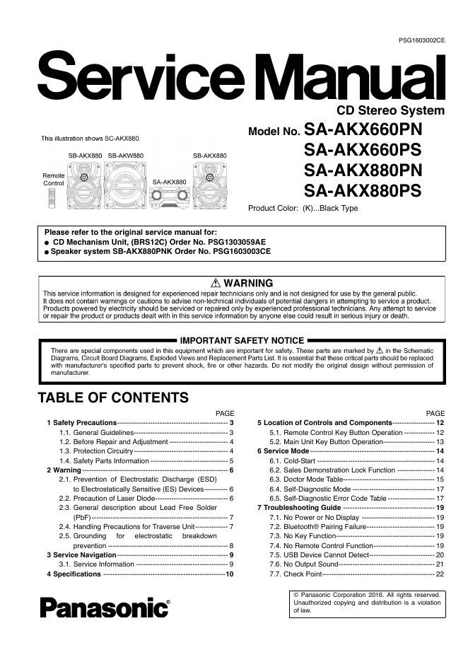
Panasonic sa akx880pn

This is the 85 pages manual for panasonic sa akx880pn.
Read or download the pdf for free. If you want to contribute, please mail your pdfs to info@audioservicemanuals.com.

Page: 1 / 85
left right
panasonic sa akx880pn

Extracted text from panasonic sa akx880pn (Ocr-read)


Page 1

PSGi BOSOOZCE

Service Manual

CD Stereo System
Model No. SA-AKX660PN

SA-AKX660PS
SA-AKX880PN
SA-AKX88OPS

Product Color: (K)...Black Type

This illustration shows SC-AKXBBO,

SB-AKX880 SB-AKW880

SB-AKX880


Remote

Control SA-AKXBBQ

0:0

'Zg

Please refer to the original service manual for:
0 CD Mechanism Unit, (BRS1ZC) Order No. PSG1303059AE
9 Speaker system SB-AKX880PNK Order No. PSG1603OOSCE

A WARNING

This service information is designed for experienced repair technicians only and is not designed for use by the general public.

It does not contain warnings or cautions to advise non-technical individuals of potential dangers in attempting to service a product.
Products powered by electricity should be serviced or repaired only by experienced professional technicians Any attempt to service
or repair the product or products dealt with in this service information by anyone else could result in serious injury or death.

IMPORTANT SAFETY NOTICE
There are special components used in this equipment which are important for safety. These parts are marked by A in the Schematic
Diagrams, Circuit Board Diagrams, Exploded Views and Replacement Parts List. It is essential that these critical parts should be replaced
with manufacturers specified pans to prevent shock, lire or other hazards. Do not modify the original design without permission of

manufacturer.


TABLE OF CONTENTS

PAGE

1 Safety Precautions ----------------------------------------------- 3

1.1. General Guidelines -----------------

1.2. Before Repair and Adjustment --

1.3. Protection Circuitry -------

1.4. Safety Parts Information

2 Warning -------------------------------------------------------------- 6
2.1. Prevention of Electrostatic Discharge (ESD)

to Electrostatically Sensitive (ES) Devices

2.2. Precaution of Laser Diode ---------------------

2.3. General description about Lead Free Solder


(PbF) ---------------------------------------------------------- 7
2.4. Handling Precautions for Traverse Unit -------------- 7
2.5. Grounding for electrostatic breakdown

prevention ----


3 Service Navigation
31. Sen/ice Information
4 Specifications -

Panasonici

PAGE
5 Location of Controls and Components .................. 12
5.1. Remote Control Key Button Operation -- 12

5.2. Main Unit Key Button Operation ---------
6 Service Mode ---
6,1. Cold-Start
6.2. Sales Demonstration Lock Function
6.3. Doctor Mode Table -----------------------
6.4. Self-Diagnostic Mode --------------
6.5. Self-Diagnostic Error Code Table
7 Troubleshooting Guide --------
7.1. No Power or No Display
7.2. Bluetooth® Pairing Failure
7.3. No Key Function -------------
7.4. No Remote Control Function---
7.5. USB Device Cannot Detect -----
7.6. No Output Soun
7.7. Check Point-

© Panasonic Corporation 2016. All rights reserved.
Unauthorized copying and distribution is a violation
of law.

Page 2

8 Disassembly and Assembly Instructions-
8.1 . Types of Screws ---------------------------
8.2. Disassembly Flow Chart ---------------------
8.3. Main Components and P.C.B. Locations
8.4. Disassembly of Top Cabinet----
8.5. Disassembly of Front Panel Uni
8.6. Disassembly of Panel P.C.B.-
8.7. Disassembly of USB P.C.B. --
8.8. Disassembly of Music Port P.C.B. --
8.9. Disassembly of Rear Panel---

8.10. Disassembly of Main P.C.B. -
8.11. Disassembly of CD Mechanism Unit--
812. Disassembly of CD Interface P.C.B.---
8.13. Disassembly of Tuner P.C.B.-
8.14. Disassembly of SMPS P.C.B.

9 Service Position ------------------
9.1. Checking of Panel P.C.B. --
9.2. Checking of Main P.C.B. and SMPS P.C.B. -

10 Block Diagram ---------
10.1. System Control -
10.2. Audio -----------
103. Power Supply

11 Wiring Connection Diagram--

12 Schematic Diagram --------------
12.1. Schematic Diagram Notes ----
12.2. Main (CD Motor Driver) Circu
12.3. Main (USB EMMC) Circuit ---------------
124. Main (SOC IO Expander) Circuit (1/2)
12.5. Main (SOC IO Expander) Circuit (2/2)
126. Main (Damp) Circuit (1/2) --
12.7. Main (Damp) Circuit (2/2) --

(
(
(
(


12.8. Main Connector) Circuit
12.9. Main DSP) Circuit --------
12.10. Main VREG Fan) Circuit (1/2)-
12.11. Main VREG Fan) Circuit (2/2)-
1212. Main (Tuner) Circuit -
12,13. SMPS Circuit (1/2) ---
12.14. SMPS Circuit (2/2) ------------------------------
12.15. CD Interface, USB and Music Port Circuit
12.16. Panel Circuit--
13 Printed Circuit Board
131. Main P.C.B. (Side A)-
13.2. Main P.C.B. (Side B)-
13.3. SMPS P.C.B. ----------
13.4. Panel, USB, CD Interface and Music Port
P.C.B. -------------------------------------------------------- 62
13.5. Tuner P.C.B. ---------------------------
14 Voltage and Waveform Measurement
14.1. Voltage Measurement-
14.2. Waveform Chart --------
15 Exploded View and Replacement Parts List
151. Cabinet Parts Location 1
15.2. Cabinet Parts Location 2---
15,3. Packaging (For SC-AKXGBOPN/PS) --
15.4. Packaging (For SC-AKXBBOPN/PS) --
15.5. Mechanical Replacement Part List -
15.6. Electrical Replacement Parts List»-