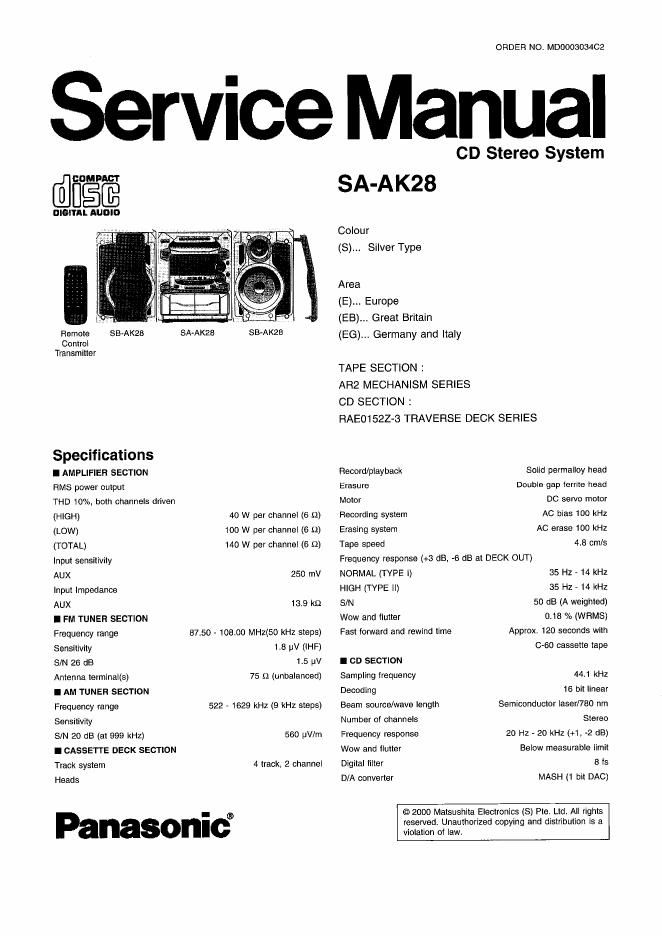
Panasonic sa ak28

This is the 78 pages manual for panasonic sa ak28.
Read or download the pdf for free. If you want to contribute, please mail your pdfs to info@audioservicemanuals.com.

Page: 1 / 78
left right
panasonic sa ak28

Extracted text from panasonic sa ak28 (Ocr-read)


Page 2

I GENERAL I SYSTEM
Power supply SC-AK28 (E) Music Center: SA-AKZB (E)
For E, EG area AC 230 V, 50HZ Speaker: SB-AK28 (E)
For EB area AC 230 V - 240 V, 50 Hz SC-AKZE (EB) Music Center: SA-AKZB (EB)
Power consumption 170 W Speaker: SB-AKZE (E)
Power consumption in standby mode SC-AK28 (EG) Music Center. SA-AK28 (EG)
Eco mode on 04 W Speaker: SB-AKZB (E)
Eco mode 011 12 W Notes:
Dimensions (W x H x D) 270 x 330 x 335 mm 1.3peclfications are subject to change without notice. Weight and
Weight 52 kg dimensions are aproximate.

2. Total harmonic distortion is measured by the digital spectrum

analyzer.
A WARNING

This service information is designed tor experienced repair technicians only and is not designed for use by the general public.

It does not contain warnings or cautions to advrsc non-technical individuals of potential dangers in attempting to service a product.
Products powered by electricity should be serviced or repaired only by experienced protessional technicians. Any attempt to service
or repair the product or products dealt with in this service iniorrnation by anyone else could result in serious injury or death

CONTENTS

Page

1 Before Repair and Adiustment

2 Protection circultry .............

3 Accessories ----------------------------

4 Handling Precautions For Traverse Deck ------------------------------- 3
5 Precautlon of Laser Blades»
5 Caution for AC Mains Lead ~-
7 Operation Procedures
3 Operation checks and Main Component Replacement

Procedu res -----------------

9 Self-Diagnostic Function
10 Description of Error Code -------------------------------------------

Page
11 CD Test Mode Function ........................................................ 19
12 Measurements and Adlustments ------------ .19
13 Illustration of 105, Transistors and Diodes -22
14 Terminal Function of lCs ....................... 723

15 Block Diagram ...................................................................... 26

16 Schematic Diagram -3a
17 Printed Circuit Board- ~47
18 Wiring Connection Diagram ------------------------------------------------- 57
19 Troubleshooting Guide ......................................................... 58
20 Parts Location and Replacement Pans List ........................ 59

1 Before Repair and Adjustment

Disconnect AC power, discharge Power Supply Capacitors 0571~C574, 0558 through a 1012, 5W resistor to ground.
DO NOT SHORTCIRCUIT DIRECTLY (with a screwdriver blade, for instance), as this may destroy solid state devices.
After repairs are completed, restore power gradually using a variac, to avoid cvercurrent.

Current consumption at AC 230V. 50 Hz in NO SIGNAL mode should be ~400mA.