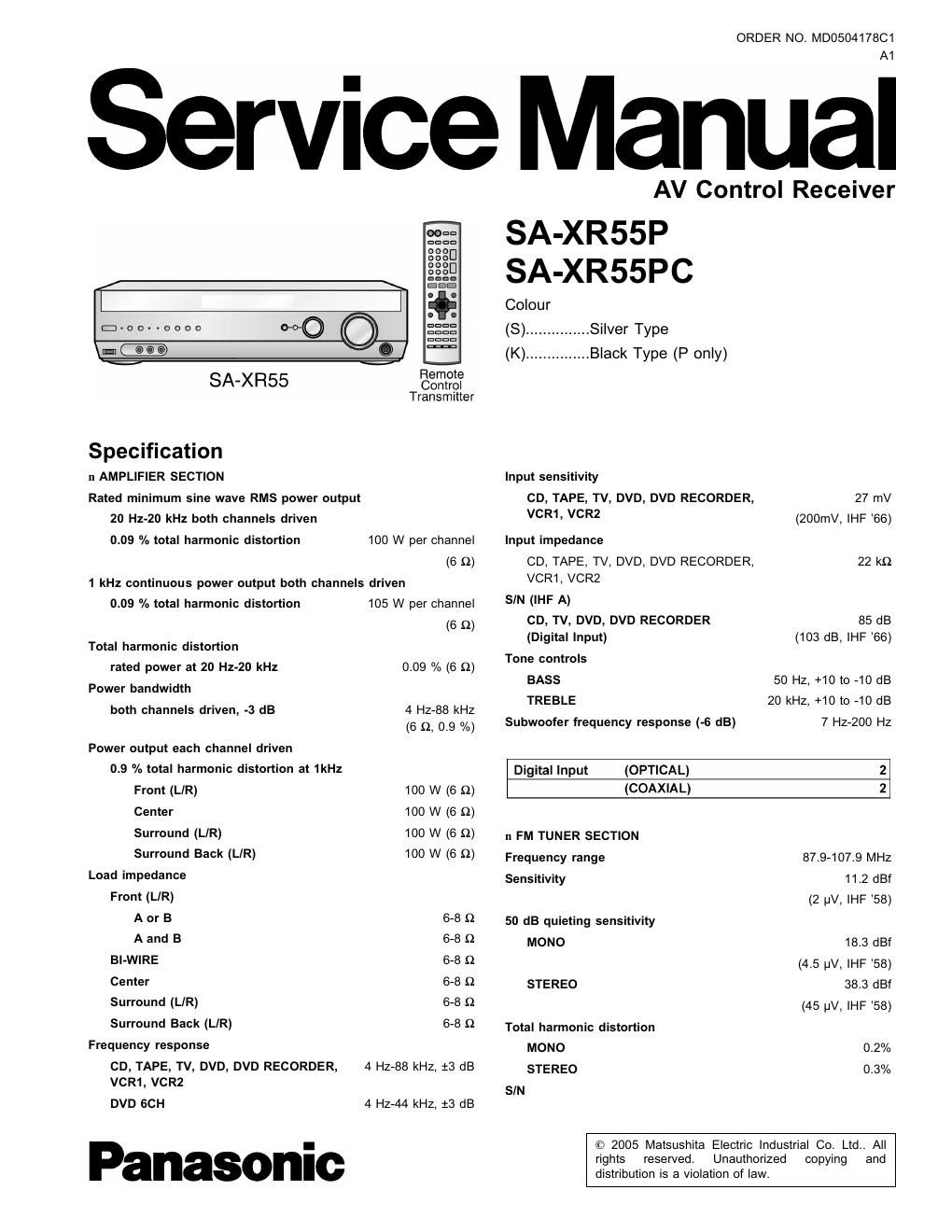
Panasonic sa xr55p

This is the 129 pages manual for panasonic sa xr55p.
Read or download the pdf for free. If you want to contribute, please mail your pdfs to info@audioservicemanuals.com.

Page: 1 / 129
left right
panasonic sa xr55p

Extracted text from panasonic sa xr55p (Ocr-read)


Page 2

SA-XR55P I SA-XRSSPC

MONO 73 dB
STEREO 67 dB
Frequency response 20 Hz-15 kHz, +1 dB,
-2 dB
Alternate channel selectivity 65 dB
Capture ratio 1.5 dB
Image rejection at 98 MHz 40 dB
Spurious response rejection at 98 MHz 75 dB
AM suppression 50 dB
Stereo separation
1 kHz 40 dB
10 kHz 30 dB

Antenna terminal 75 Q (unbalanced)

Input TV, DVD, DVD
RECORDER
Output TV MONITOR

Component Video
Input TV, DVD, DVD
RECORDER
Output TV MONITOR

n GENERAL

Power supply AC 120 V, 60 Hz
Power consumption 135 W
Dimensions (W x H x D) 430 mm x 107.5 mm x
394 mm

(16-15/16" X 4-7/32 X 15-1/2")

Mass 4.6 kg (10.1 lb.)
11 AM TUNER SECTION
Frequency range 530-1710 kHz n DIN POWER
Senslt'V'ty 2° VI 33° W 1 kHz, T.H. D 1% 2 x 100 W (6 Q)
Selectivity 55 dB
IF rejection at 1000 kHz 50 dB

Power consumption in standby mode: 0.2 W
11 VIDEO SECTION
Output voltage at 1 V input (unbalanced) 1:0.1 Vp-p Notes:
Maximum input voltage 1.5 Vp-p 1. Specifications are subject to change without notice.
Input/output impedance 75 0 Mass and dimensions are approximate.
S-Video 2. Total harmonic distortion is measured by the digital spectrum

analyzer.
A WARNING

This service information is designed for experienced repair technicians only and is not designed for use by the general public.

It does not contain warnings or cautions to advise non-technical individuals of potential dangers in attempting to service a product.
Products powered by electricity should be serviced or repaired only by experienced professional technicians. Any attempt to service
or repair the product or products dealt with in this service information by anyone else could result in serious injury or death.

CONTENTS

1 SAFETY PRECAUTIONS
1.1. GENERAL GUIDELINES

2 Before Repair and Adjustment ............................................... 5
3 Protection Circuitry ----------------------------------------------------------------- 5
4 Handling the Lead-free Solder ------------------------------------------------ 5

4.1. About lead free solder (PbF) .......................................... 5
5 Accessories ............................................................... 6
6 Operating Instructions ............................................................ 7

6.1. Main Unit -----

6.2. Remote Control -

6.3. Home Theater Connections -9
6.4. Other Connections ------------------------------------------------------- 14
7 Disassembly and Main Component Replacement Procedures

and Operational Check --------------------------------------------------------- 17
7.1. Disassembly flow chart ------------------------------------------------- 17
7.2. P.C.B. Positions ------------------------------------------------ 18
7.3. Disassembly of Top Cabinet. -------------------------------------- 18
7.4. Checking for the DSP P.C.B. (Side MB) and Main P.C.B.

(Side A). ---------------------------------------------------------------------- 19

7.5. Disassembly and Checking of Main P.C.B. (Side B)-
7.6. Disassembly of Tuner Pack and Tuner Extent P.C.B

7.7. Disassembly and Checking of Speaker P.C.B.
7.8. Disassembly and Checking of Component Video P.C.B.-21
7.9. Disassembly and Checking of Video & Optical P.C.B. ----22

7.10. Disassembly of Rear Panel ------------------------------------------ 22
7.11. Disassembly and Checking of Input P.C.B. ................... 23
7.12. Disassembly of Front Panel .......................................... 24

7.13. Disassembly and Checking of Panel P.C.B Volume
P.C.B. and Headphone P.C.B.
7.14. Disassembly and Checking of Power P.C.B.

8 Self Diagnosis Display Function --------------

8.1. Automatically Displayed Error Codes ............................ 27
8.2. Display Details ------------------------------------------------------------- 27
8.3. Returning to Normal Display ----------------- 27
8.4. Overload/Shutdown Detection intenal Condition ------------- 27
8.5. Overload/Thermal Detection Display ............................. 27

8.6. Activating Self Diagnosis Function (Servicing Mode) ------ 27
8.7. Analog 6.1 CH Output Check Method --------------------------- 28