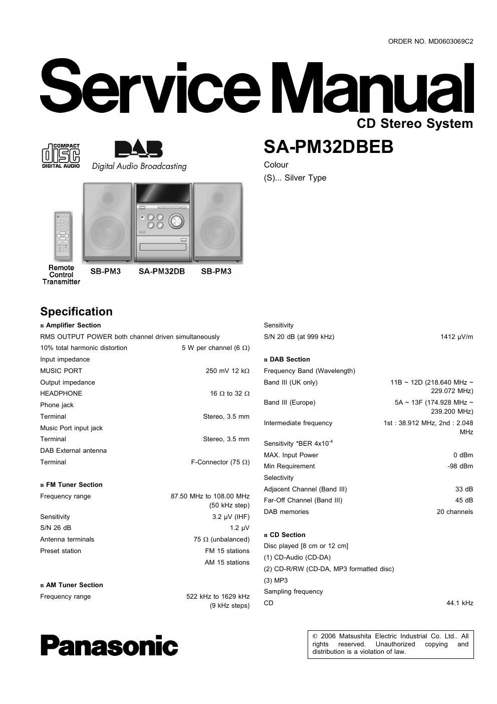
Panasonic sa pm 32 dbeb service manual

This is the 76 pages manual for panasonic sa pm 32 dbeb service manual.
Read or download the pdf for free. If you want to contribute, please mail your pdfs to info@audioservicemanuals.com.

Page: 1 / 76
left right
panasonic sa pm 32 dbeb service manual

Extracted text from panasonic sa pm 32 dbeb service manual (Ocr-read)


Page 2

SA-PMZZDBEB

MP3 32 kHz, 44.1 kHz, 48 kHz
Bit rate

MP3 32 kbps to 384 kbps
Decoding 16/20/24 bit linear
Pickup

Beam source Semiconductor laser
Wavelength 785 nm
Laser power CLASS 1
Audio output (Disc)

Number of channels 2 channel

Frequency response 20 Hz to 20 kHz (+1, -2dB)

Wow and flutter Below measurable limit
Digital filter 8 fs

D/A converter MASH (1 bit DAC)

in General

Power supply AC 230 to 240 V, 50 Hz

Power consumption 25 W
Dimensions (W x H x D) 165 mm x 227 mm x 327 mm
Mass 2.8 kg

+5°C to +35°C
5% to 90% RH (no condensation)
0.8 W

Operating temperature range
Operation humidity range

Power consumption
mode

in standby

Notes :

1. Specifications are subject to change without notices. Mass and
dimensions are approximate.

2. Total harmonic distortion is measured by the digital spectrum
analyzer.

n System : SC»PM32DBEBS Music center: SA-PM32DBEBS

Speaker: SB-PM3EG-M

A. WARNING

This service information is designed for experienced repair technicians only and is not designed for use by the general public.

It does not contain warnings or cautions to advise non-technical individuals of potential dangers in attempting to service a product.
Products powered by electricity should be serviced or repaired only by experienced professional technicians. Any attempt to service
or repair the product or products dealt with in this sen/ice information by anyone else could result in serious injury or death.

CONTENTS

Page
1 Safety Precautions ------------------------------------------------------------------ 4
1.1. General Guidelines -------------------------------------------------------- 4
1.2. Caution for AC Cord ------------------------------------------------------ 5
1.3. Before Repair and Adjustment ---------------------------------------- 6
1.4. Protection Circuitry --------------------------------------------------------- 6
2 Prevention of Electro Static Discharge (ESD) to
Electrostatically Sensitive (ES) Devices --------------------------------- 7

3 Precaution of Laser Diode .....................
4 Handling Precautions For Traverse Deck-
5 Handling the Lead-free Soider ...............

5.1. About lead free solder (PbF) ......................................... 10
6 Accessories -------------------------------------------------------------------------- 11
7 Operating Instructions Procedures --------------------------------------- 12
7.1. Main Unit Operation ----------------------------------------------------- 12
7.2. Remote Control Operation ............................................ 13
7.3. Disc Information .................................................. 13
8 Self diagnosis and special mode setting -14

8.1. Special Mode Tabl 4
8.2. Error Code Table -- .15
9 Assembling and Disassembling ........................................... 15
9.1. Caution ................................................ 15
9.2. Disassembly flow chart ------------------------------------------------- 17
9.3. Main Parts Location Diagram ---------------------------------------- 13
9.4. Disassembly of Side Panel L a R ................................. 19
9.5. Disassembly of Top Cabinet Unit ---------------------------------- 19
9.6. Disassembly of Headphone P.C.B. ............................... 20

9.7. Disassembly of Front Panel -----
9.8. Disassembly of DAB Module unit
9.9. Disassembly of Panel P.C.B. ------

Page
9.10. Disassembly of Rear Panel .......................................... 21
9.11. Disassembly of Tuner Pack ------------------------------------------ 22
9.12. Disassembly of Main P.C.B. ......................................... 22
9.13. Disassembly of Power P.C.B. --------------------------------------- 22
9.14. Disassembly of Speaker Terminal P.C.B_ ...................... 23
9.15. Disassembly of Transformer P_C_B, ------------------------------ 24
9.16. Disassembly of CD Mechanism ------------------------------ 24

9.17. Disassembly of Traverse Unit, Driving Gear, and Cam

Gear (CD Mechanism Unit) --
9.18. Disassembly of Optical Pickup (CD Mechanism Unit)
9.19. Disassembly of Traverse Gear A and Traverse Gear B

(CD Mechanism Unit) --------------------------------------------------- 2g

10 Service Fixture and Tools ----------------------------------------------------- 30

11 Service Positions ......................................................... 30

11.1. Checking and Repairing Headphone P.C.B. .................. 30
11.2. Checking and Repairing of DAB Module Unit and Panel

P.C.B. ------------------------------------------------------------
11.3. Checking and Repairing of Transformer P.C.B.
11.4. Checking and Repairing of Main P.C.B. --

11.5. Checking and Repairing of co Servo p_c_B_ ................. 34
11.6. Checking and Repairing of Speaker Terminal P.C.B. ----- 35
11.7. Cheeklng and Repairing of Power P.C.B. .............. 35
12 Voltage Measurement and Waveform Chart ......................... 37
12.1. Voltage Measurement .................................................. 37
12.2. Waveform -------------------------------------------------------------------- 40
13 Wiring Connection Diagram -------------------------------------------------- 41

14 Block Diagram ------

15 Notes of Schematic iagram

16 Schematic Diagram .............