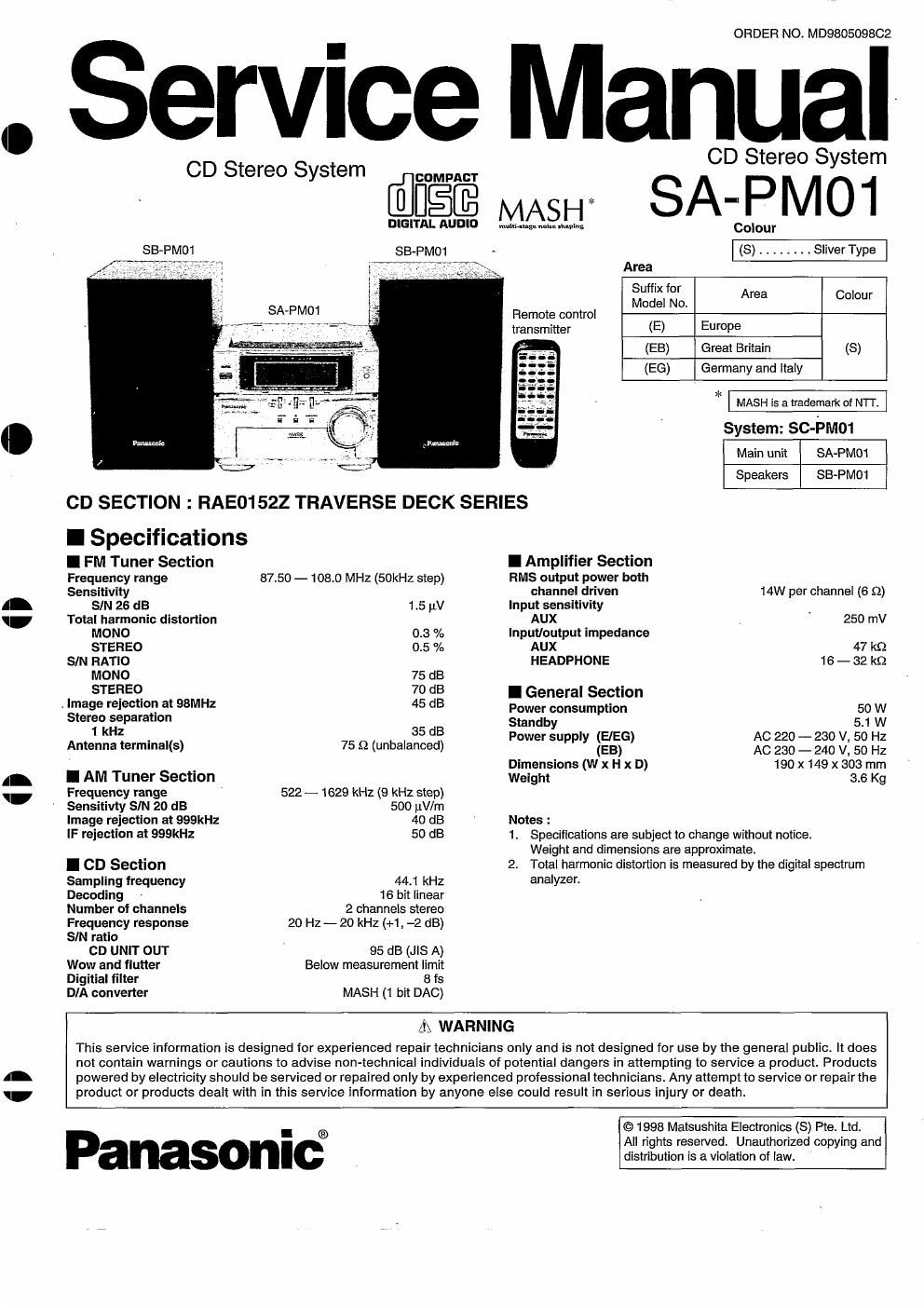
Panasonic sa pm 01 service manual

This is the 52 pages manual for panasonic sa pm 01 service manual.
Read or download the pdf for free. If you want to contribute, please mail your pdfs to info@audioservicemanuals.com.

Page: 1 / 52
left right
panasonic sa pm 01 service manual

Extracted text from panasonic sa pm 01 service manual (Ocr-read)


Page 1

ii

ORDER NO. MD980509802

Service Manual

CD Stereo System CD Stereo System

I AM Tuner Section

Frequency range
Sensitivty SIN 20 dB
Image rejection at 999kHz
IF rejection at 999kHz

I CD Section
Sampling frequency
Decoding
Number of channels
Frequency response
SIN ratio

CD UNIT OUT
Wow and flutter
Digitial filter
DIA converter

522 - 1629 kHz (9 kHz step)
500 uV/m

40 dB

50 dB

44.1 kHz

16 bit linear

2 channels stereo

20 Hz-20 kHz (+1, -2 dB)

95 dB (JIS A)
Below measurement limit
8 ts

MASH (1 bit DAC)

Dimensions (W x H x D)
Weight

Notes :

1. Specifications are subject to change without notice.

COMPACT
MAS H * S A " I M O 1
DIGITAL Aunlo mun-ms. new; Colour
seen/[01 SB PMO1 - (S) ------- Sliver Type
- Area
Suffix for
Model No. Area C°l°ur
Remote control
transmitter (E) Europe
(EB) Great Britain (3)
(EG) Germany and Italy
*
System: SC-PM01
Main unit SA-PMO1
Speakers SB-PM01
CD SECTION : RAE01522 TRAVERSE DECK SERIES
I Specifications
I FM Tuner Section I Amplifier Section
Frequency range 87.50 - 108.0 MHz (50kHz step) RMS output power both
Sensitivity channel driven 14W per channel (6 Q)
SIN 26 dB 1.5 uv Input sensitivity
Total harmonic distortion AUX 250 mV
MONO 0.3 % Input/output impedance
STEREO 0.5 % AUX 47 k5)
SIN RATIO HEADPHONE 16 - 32 k9
MONO 75 dB
STE'TEO, 70 B I General Section
. Image rejection at SBMHz 45 dB Power consumption 50 W
Stereo separation 53"de 51 W
1 k: . 35 33 Power supply (EIEG) AC 220 - 230 v, 50 Hz
Antenna termmal(s) 75 £2 (unbalanced) EB AC 230 _ 240 V, 50 Hz

190x 149 X 303 mm

Weight and dimensions are approximate.
2. Total harmonic distortion is measured by the digital spectrum

analyzer.

3.6 Kg

I\ WARNING

This service information is designed for experienced repair technicians only and is not designed for use by the general public. It does
not contain warnings or cautions to advise nonvtechnical individuals of potential dangers in attempting to service a product. Products
powered by electricity should be serviced or repaired only by experienced professional technicians, Any attempt to service or repair the
product or products dealt with in this service information by anyone else could result in serious injuw or death.

Panasonic®

©1998 Matsushita Electronics (S) Pte. Ltd.
All rights reserved. Unauthorized copying and
distribution is a violation of law

Page 2

SA-PM01

I Contents

ACCESSORIES ................................................
' HANDLE PRECAUTIONS FOR TRAVERSE DECK
- PRECAUTION OF LASER DIODE
- CAUTION FOR AC MAINS LEAD
0 CONNECTIONS ........................
- FRONT PANEL CONTROLS
° SETTING THE TIME

0 LISTENING TO CDS
' OPERATION CHECKS
- SELF-DIAGNOSTIC DISPLAY FUNCTION
- SCHEMATIC DIAGRAM ..
' PRINTED CIRCUIT BOARD

PAGE
- TERMINAL GUIDE OF lC's TRANSISTORS AND DIODES ,,,,,,, 34
' TERMINAL FUNCTION OF ICS ......................................... 35 ~ 37
' WIRING CONNECTION DIAGRAM 38

' BLOCK DIAGRAM...
- TROUBLESHOOTING GUIDE.
0 LOADING MECHANISM PARTS LIST
- LOADING MECHANISM PARTS
' CABINET PARTS LOCATIONS
' REPLACEMENT PARTS LIST.
- RESISTORS & CAPACITORS ..............
' PACKING MATERIALS & ACCESSORIES
- PACKAGING ........................................

39 ~ 42
43

I Accessories

- AC power supply cord ............................... 1 - FM indoor antenna ..................................... 1 - Remote control transmitter (EUR645401) .. 1
For United Kingdom For Others For United Kingdom For others
(RJA0053»1 X) (RSAOOO7) (RSAOOOB)

(RJAOOl 9-2K)

- Antenna plug adaptor (SJPQOOQ) ............... 1
(United Kingdom only)

- AM loop antenna set (RSAOOZS) ................ 1

. Remote control batteries 2
Note: These are available on sales route.

@

I Handling Precautions for Traverse Deck

The laser diode in the traverse deck (optical pickup) may break down due to potential difference caused by static electricity of clothes or human body.

So. be careful of electrostatic breakdown during repair of the traverse deck (optical pickup).

- Handling of traverse deck (optical pickup)

1. Do not subject the traverse deck (optical pickup) to static electricity
as it is extremely sensitive to electrical shock.

2. The short land between the No.4 (LD) and No.5 (GND) pins on the
flexible boards (FPC) is shorted with a solder build-up to prevent
damage to the laser diode.

To connect to the PC board, be sure to open by removing the solder
build-up, and finish the work quickly.

3. Take care not to apply excessive stress to the flexible board (FFC
board).

4. Do not turn the variable resistor (laser power adjustment). It has
already been adjusted

- Grounding for electrostatic breakdown prevention

1. Human body grounding
Use the anti-static wrist strap to discharge the static electricity from
your body,

2. Work table grounding
Putaconducive material (sheet) orsteel sheet on the area where the
traverse deck (optical pickup) is placed. and ground the sheet.

Caution:

The stan'c electricity of your clothes will not be grounded through the
wrist strap, So, take care not to let your clothes touch the traverse deck
(optical pickup).

FFC board Lens (Do not touch)

(Handle it oarelully)

Vanable resistor
(Do not turn)

Wrist strap
(Anti-static bracelet) /

I

H

H