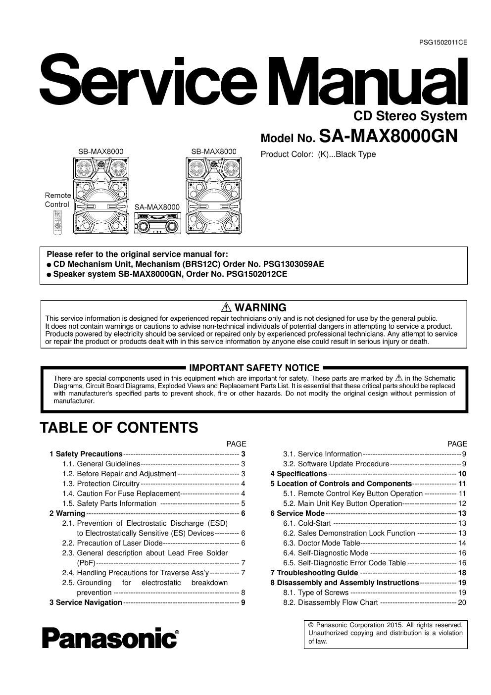
Panasonic sa max8000gn service manual

This is the 104 pages manual for panasonic sa max8000gn service manual.
Read or download the pdf for free. If you want to contribute, please mail your pdfs to info@audioservicemanuals.com.

Page: 1 / 104
left right
panasonic sa max8000gn service manual

Extracted text from panasonic sa max8000gn service manual (Ocr-read)


Page 1

PSG1502011CE

Service Manual

SB-MAXSOOO

E


Remote ,

00"01 SA-MAXSOOO

r
i
._J

CD Stereo System
Model No. SA-MAXSOOOGN

Product Color: (K)...Black Type

Please refer to the original service manual for:

9 CD Mechanism Unit, Mechanism (BRS12C) Order No. PSG1303059AE
0 Speaker system SB-MAXBOOOGN, Order No. PSG150201ZCE

A WARNING

This service information is designed for experienced repair technicians only and is not designed for use by the general public.

It does not contain warnings or cautions to advise non-technical individuals of potential dangers in attempting to service a product.
Products powered by electricity should be serviced or repaired only by experienced professional technicians. Any attempt to service
or repair the product or products dealt with in this service information by anyone else could result in serious injury or death.

IMPORTANT SAFETY NOTICE

There are special components used in this equipment which are important for safety. These parts are marked by A in the Schematic
Diagrams, Circuit Board Diagrams, Exploded Views and Replacement Parts List. It is essential that these critical parts should be replaced
with manufacturers specified parts to prevent shock, tire or other hazards. Do not modify the original design without permission of

manufacturer.

TABLE OF CONTENTS

PAGE
1 Safety Precautions ----------------------------------------------- 3
1.1. General Guidelines ---------------
1.2. Before Repair and Adjustment
1.3. Protection Circuitry ------------------
1.4. Caution For Fuse Replacement--
1.5. Safety Parts Information
2 Warning -----------------------------
2.1. Prevention of Electrostatic Discharge (ESD)
to Electrostatically Sensitive (ES) Devices--
2.2. Precaution of Laser Diode --------------------
2.3. General description about Lead Free Solder

(PbF) ---------------------------------------------------------- 7
2.4. Handling Precautions for Traverse Ass'y ------------ 7
2.5. Grounding for electrostatic breakdown

prevention


3 Service Navigation

Panasonict

PAGE

3.1. Service Information ---------------------------------------- 9
3.2. Software Update Procedure

4 Specifications -------------------------
5 Location of Controls and Components -----
5.1. Remote Control Key Button Operation
5.2. Main Unit Key Button Operation

6 Service Mode--
6.1. Cold-Start
6.2. Sales Demonstration Lock Function
6.3. Doctor Mode Table -----------------------
6.4. Self-Diagnostic Mode ----------------
6.5. Self-Diagnostic Error Code Table -

7 Troubleshooting Guide -----------------------
8 Disassembly and Assembly Instructions--
8.1. Type of Screws -------------
8.2. Disassembly Flow Chart -

© Panasonic Corporation 2015. All rights reserved.
Unauthorized copying and distribution is a violation
of law.

Page 2

10 Block Diagram ....................

11 Wiring Connection Diagram__
12 Schematic Diagram ..............

13 Printed Circuit Board

8.3. Main Components and P.C.B. Locations
8.4. Disassembly of Top Cabinet ----------------
8.5. Disassembly of Fan Unit ---------
8.6. Disassembly of Front Panel Uni
8.7. Disassembly of FL Display P.C.B. -----
8.8. Disassembly of Illumination Jog P.C.B.
8.9. Disassembly of Illumination Left P.C.B
8.10. Disassembly of BT&NFC P.C.B --------
8.11. Disassembly of Volume Jog P.C.B.----
8.12. Disassembly of Illumination Right P.C.B
8.13. Disassembly of USB P.C.B. -
8.14. Disassembly of Mic P.C.B.-
8.15. Disassembly of DJ Cabinet Unit--
8.16. Disassembly of Button Left P.C.B. --
8.17. Disassembly of Multi Control P.C.B.
8.18. Disassembly of Button Right P.C.B.
8.19. Disassembly of SMPS P.C.B. --------
8.20. Disassembly of Inner Chassis Unit -
8.21. Disassembly of Main P.C.B. -------
8.22. Disassembly of CD Mechanism Unit--
8.23. Disassembly of CD Interface P.C.B.
9 Service Position --------------------------------
9.1. Checking of FL Display P.C.B., Button Left
P.C.B., Button Right P.C.B. and Multi Control
P.C.B. ----------------------

9.2. Checking of SMPS P.C.B
9.3. Checking of Main P.C.B.-


10.1. System Control -
10.2. Audio -----------
10.3. Power Supply

12.1. Schematic Diagram Notes
12.2. Main (IO Expansion) Circuit--
12.3. Main (Fan LED) Circuit --
12.4. Main (DSP) Circuit --------
12.5. Main (Amp BTL) Circuit (1/2)-
12.6. Main (Amp BTL) Circuit (2/2)-
12.7. Main (MICON) Circuit (1/2)
12.8. Main (MICON) Circuit (2/2)
12.9. Main (Amp Single) Circuit (1/2)

( (

(

(

(

(

(

12.10. Main Amp Single) Circuit 2/2)-
12.11. Main FE) Circuit ................

12.12. Main Karaoke) Circuit ..............
12.13. Main Digital Power) Circuit (1/2)-
12.14. Main Digital Power) Circuit (2/2)-
12.15. Main USB) Circuit ...................

12.16. Main (AUX Tuner) Circuit ------------------------------ 61
12.17. Illumination Left, Illumination Right,
Illumination Jog and Volume Jog Circuit ----------- 62
12.18. FL Display Circuit - --63
12.19. Button Left Circuit- 6--4
12.20. Button Right and Multi Control Circuit ---65


12.21. Mic Circuit ------------------------------------
12.22. USB and CD Interface Circuit
12.23. SMPS Circuit (1/2) --------------
12.24. SMPS Circuit (2/2)

13.1. Main P.C.B. (Side A)-
132. Main P.C.B. (Side B)---

14 Voltage and Waveform Measurement

15 Exploded View and Replacement Parts List--

13.3. Illumination Left, Illumination Right and FL
Display P.C.B. -------------------------------------------- 72
13.4. Button Left, Button Right, Mic and USB P.C.B. -- 73
13.5. Volume Jog, Illumination Jog, Multi Control
and CD Interface P.C.B.-
13.6. SMPS P.C.B. ------------

14.1. Voltage Measurement --------------
14.2. Waveform Chart ------------------------------


15.1. Cabinet Parts Location 1--
15.2. Cabinet Parts Location 2
15.3. Cabinet Parts Location 3---
15.4. Packaging -----------------------------
15.5. Mechanical Replacement Part List-
15.6. Electrical Replacement Part List --------------------- 91