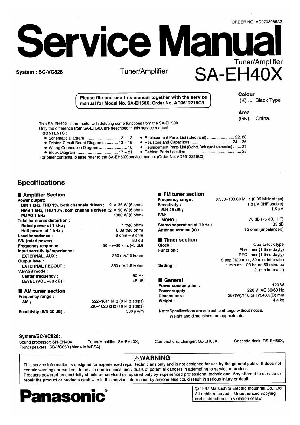
Panasonic sa eh 40 x service manual

This is the 29 pages manual for panasonic sa eh 40 x service manual.
Read or download the pdf for free. If you want to contribute, please mail your pdfs to info@audioservicemanuals.com.

Page: 1 / 29
left right
panasonic sa eh 40 x service manual

Extracted text from panasonic sa eh 40 x service manual (Ocr-read)


Page 2

SA-EH4OX

lSchematic Diagram _

Page Page
E MAIN CIRCUIT7 ~12
fl POWER TRANSFORMER (A) CIRCUIT ................ 12
5 POWER SUPPLY CIRCUIT.....................
m POWER TRANSFORMER (a) CIRCUIT.

TUNER CIRCUIT ..
E] OPERATION CIRCUIT
MIC JACK CIRCUIT
E IN/OUT TERMINAL CIRCUIT.

Notes:

0 $901 : Power STANDBY d) ION" switch (POWER STANDBY (b ION)
0 $902 : Clock/timer switch (CLOCK/TIMER)

O 8903 : Record timer switch (9 REC)

I 5904 : Play timer switch ( G) PLAY)

0 $905 : Tuning mode select switch (TUNING MODE)

0 $906 : Set switch (SET)

0 $907 : FM mode select switch (FM AUTO/MONO)

o 5908 : Source input select switch (INPUT SELECTOR)
I 5909 : Tuning down switch (TUNING v)

0 S910 : Tuning up switch (TUNING A)

0 5911 : Tuner/band select switch (TUNER/BAND)

O 8912 : V.bass switch (V.BASS)

o 8913 : Karaoke switch (KARAOKE)

0 $914 : Echo switch (ECHO)

o 8915 : Vibrate switch (VIBRATE)

0 S916 : Chorus switch (CHORUS)

0 5917 : Wide switch (WIDE)

o 8918 : Key control on/oft switch (KEY CON(CD) ON/OFF)
0 $919 : b switch ( b )

0 $920 : # switch ( # )

o VR401 : Microphone volume control (MIC VOL)

0 VR901 : Volume control (VOLUME)

0 This schematic diagram may be modified at any time with the development of new technology.

0 Indicated voltage values are the standard values for the unit measured by the DC electronic circuit tester (high-impedance) with
the chassis taken as standard. Theretore, there may exist some errors in the voltage values, depending on the internal impedance
at the DC circuit tester.

No mark : FM ( ) 2 AM

0 Important safety notice:
Components identified by [2; mark have special characteristics important for safety.
Furthermore, special parts which have purposes of tire-retardant (resistors), high-quality sound (capacitors), low-noise (resistors),
etc. are used. When replacing any of components, be sure to use only manufacturers specified parts shown in the parts list.

0 Caution!
IC and LSI are sensitive to static electricity.
Secondary trouble can be prevented by taking care during repair.
Cover the parts boxes made of plastics with aluminum foil.
Ground the soldering iron.
Put a conductive mat on the work table.
Do not touch the legs of IC or LSI with the lingers directly.

0 Voltage and signal line

- : Positive voltage line nut-nu 2 Negative voltage line
: AM signal Line mum : Mic signal Line

II I . : AM 050 signal line |::> : FM signal line

an u :> : FM 030 signal line

-2-