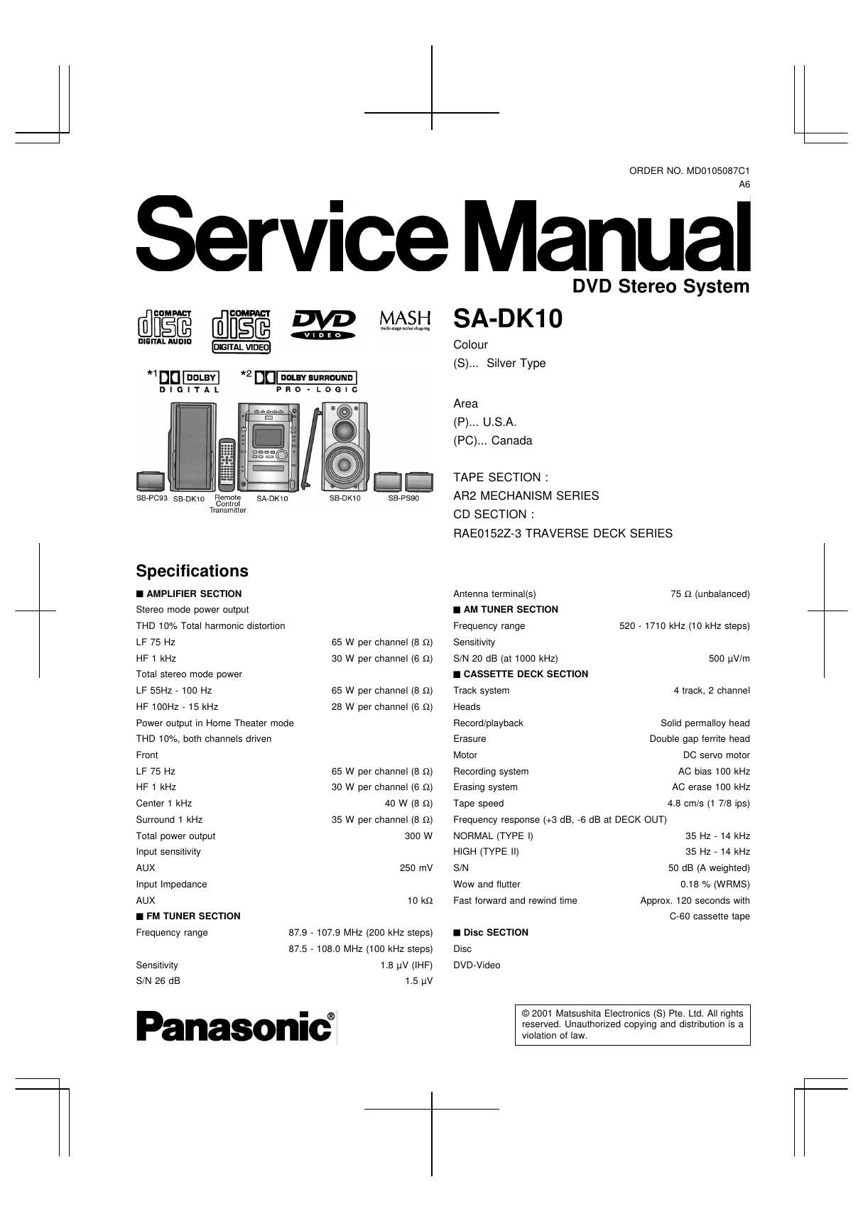
Panasonic sa dk 10 service manual

This is the 107 pages manual for panasonic sa dk 10 service manual.
Read or download the pdf for free. If you want to contribute, please mail your pdfs to info@audioservicemanuals.com.

Page: 1 / 107
left right
panasonic sa dk 10 service manual

Extracted text from panasonic sa dk 10 service manual (Ocr-read)


Page 2

8 cm/12 cm single sided, single layer I GENERAL
8 cm/12 cm single sided, double layer Power supply AC 120 V, 60Hz
8 cm/12 cm double sided, double layer Power consumption 161 W
(One layer per side) Power consumption in standby mode
Video CD/CD 8 cm/12 cm 161 W
Video Dimensions (W x H x D) 215.4 X 315 X 350 mm
Signal system NTSC 8 1/ " X 12 13/32" X 13 25/32"
Output level Mass (7.8 kg) 17.2 lb
Composite video 1 Vp-p (75 Q)
S-Video Y 1 Vp-p (75 n) I SYSTEM
S-Video C 0.286 Vp-p (75 Q/NTSC) SC-DK10(P) Music Center: SA-DK10(P)
Audio Front Speaker: SB-DK10(P)
Sampling frequency Surround Speaker: SB-PS90(P)
CD 44.1 kHz Center Speaker: SB-P093(P)
DVD 48kH2/96 kHz SC-DK10(PC) Music Center: SA-DK10(PC)
Decoding 16/20/24 bit linear Front Speaker: SB-DK10(P)
Wow and flutter Below measurable limit Surround Speaker: SB-PSSO(P)
D/A converter Delta-sigma DAC) Center Speaker: SB-P093(P)
Pick up Notes:
Beam source Semiconductor Laser 1.Specifications are subject to change without notice. Mass and
Wavelength dimensions are aproximate.
DVD 658 nm 2. Total harmonic distortion is measured by the digital spectrum
VCD/CD 790 nm analyze"

A WARNING

This service information is designed for experienced repair technicians only and is not designed for use by the general public

It does not contain warnings or cautions to advise non-technical individuals of potential dangers in attempting to service a product.
Products powered by electricity should be serviced or repaired only by experienced professional technicians. Any attempt to service
or repair the product or products dealt with in this service information by anyone else could result in serious injury or death.

CONTENTS

1 Satety Precaution-
2 Before Repair and Adjustment

3 Protection Circuitry ..........................

4 Accessories

5 Handling Precautions For Traverse Deck

6 Precaution of Laser Diode
7 Operation Procedures

....................................... 3

8 Disassembly and Main Component Replacement Procedures

....................................... 9

9 Measurements and Adjustments --

10 Illustration of ICS, Transistors and Diodes
11 Terminal Function of lC's ----------------------------------------------------- 25
12 Block Diagram ---------------------------------------------------------------------- 26
13 Schematic Diagram
14 Printed Circuit Board-
15 Wiring Connection Diagram

16 Parts Location and Replacement Parts List ------------------------- 83