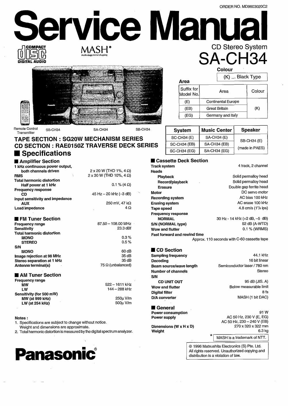
Panasonic sa ch 34 service manual

This is the 21 pages manual for panasonic sa ch 34 service manual.
Read or download the pdf for free. If you want to contribute, please mail your pdfs to info@audioservicemanuals.com.

Page: 1 / 21
left right
panasonic sa ch 34 service manual

Extracted text from panasonic sa ch 34 service manual (Ocr-read)


Page 2

sA-CH34
A WARNING

Th is service information is designed forexpen'ense repairtechnicians onlyand is not designed foruse by the general public, It does not contain wamings
or cautions to advise non-technical individualsof potential dangers in attempting to sen/ice a product Products powered by electricity should be sen/iced
or repaired only by experienced p rotessional tech nicians. Any attem pt to service or repairthe p roductorproducts dealt with in thisservice information
by anyone else could result in serious injury or death.

I Contents Page Page
BEFORE REPAIR AND ADJUSTMENT .......................... WIRING CONNECTION DIAGRAM .. 20 ~ 21

HANDLING PRECAUTIONS FOR TRAVERSE DECK 22 ~ 25
PROTECTION crncurrnv ............ 26 - 32
PRECAUTION 0F LASER DIODE as ~ 45

2

2 BLOCK DIAGRAM ..............
3 PRINTED CIRCUIT BOARD
5 SCHEMATIC DIAGRAM ..
4

5

10

CAUTION FOR AC MAINS LEAD TROUBLESHOOTING GU 46
BEFORE MOVING OR SHIPPING THIS UNIT. MECHANISM PARTS LIST ..... . 47
OPERATIONCHECKSANDMAIN COMPONENTREPLACEMENT 5 ~ MECHANISM PARTS LOCATION (RAAO910) 48 ~ 49
SELF-DIAGNOSTIC DISPLAY FUNCTION 11 ~ 12 CD LOADING UNIT PARTS LIST .. 50
CD TEST MODE FUNCTION .................... 13 PACKAGING ............................... 50
RELIABILITY TEST MODE FOR CD/CD CHANGER .. 14 CD LOADING UNIT PARTS LOCATION . . 51
MEASUREMENTS AND ADJUSTMENTS.. 15 CABINET PARTS LOCATION 52 ~ 53
TERMINALFUNCTION OFICS ................ 16~ 18 REPLACEMENTPARTS LIST 54-56
TERMINAL GUIDE OF ICs, TRANSISTORS AND DIODES. 19 RESISTORS 8t CAPACITORS . 57 ~ 60

I Before Repair and Adjustment

Disconnect AC power, discharge both Power Supply Capacitors 0522 and 0523 through a 109 , 5W resistor to ground.
DO NOT SHORT-CIRCUIT DIRECTLY (with a screwdriver blade, for instance), as this may destroy solid state devices.
After repairs are completed, restore power gradually using a variac, to avoid overcurrent.

Current consumption at 280V, 50 Hz in NO SIGNAL mode should be ~250mA.

I Handling Precautions for Traverse Deck

The laser diode in the traverse deck (optical pickup) may break down due to
potential difference caused by static electricity of clothes or human body. 4 .
So, be careful of electrostatic breakdown during repair of the traverse deck gfiflfifif

Lens (Do not touch)

(optical pickup). _ \ / Opticalpickup
/
- Handling of traverse deck (optical pickup) E

1.Do not subject the traverse deck (optical pickup) to static
electricity as it is extremely sensitive to electrical shock.

2.To prevent the breakdown of the laser diode, an antistatic FPCboard
shorting pin is inserted into the flexible board (FPC board). ma'°°°'"
When removing or connecting the short pin, finish the job in as
short time as possible.


3.Take care not to apply excessive stress to the flexible board /
(FPC board). .
4. Do not turn the variable resistor (laser power adjustment). It has
already been adjusted. , /
' . Be sure to short this position
- Grounding for electrostatic breakdown prevention (Usethe shorting rzin orclipl

1.Human body grounding
Use the anti-static wrist strap to discharge the static
electricity from your body.

2.Work table grounding .
Put a conductive material (sheet) or steel sheet on the .
area where the traverse deck (optical pickup) is placed,
and ground the sheet.

Wrist strap
(Antistatic bracelet)

1 Mo
Caution :

The static electricity of your clothes will not be grounded
through the wrist strap. So, take care not to let your clothes
touch the traverse deck (optical pickup).

ern plate or some metals
to conduct electricity