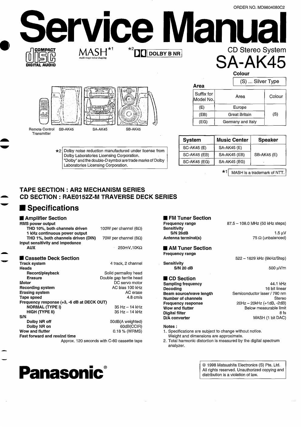
Panasonic sa ak 45 service manual

This is the 76 pages manual for panasonic sa ak 45 service manual.
Read or download the pdf for free. If you want to contribute, please mail your pdfs to info@audioservicemanuals.com.

Page: 1 / 76
left right
panasonic sa ak 45 service manual

Extracted text from panasonic sa ak 45 service manual (Ocr-read)


Page 2

SA-AKLI

AWARNING

This service Information is designed for experiense repairtechnicians only and is not designed for use by the general public. It does not contain
warnings or cautions to advise non-technical individuals of potential dangers In attempting to service a product. Products powered by electricity
should be serviced or repaired only by experienced professional technicians. Any attempt to service or repair the product or products dealt with
in this service information by anyone else could result in serious injury or death.

IGeneraI
Power consumption 133W
Power supply

for E, E6 AC 230V, 50 Hz

for EB AC 230 -- 240V, 50 HZ
Dimensions (W x H x D) 270 x 336 x 347 mm
Weight 7.1 kg
I contents Page
BEFORE REPAIR AND ADJUSTMENT 2 TERMINAL FUNCTION OF ICs .....
PROTECTION CIRCUITRY ........ 2 WIRING CONNECTION DIAGRAM
CAUTION FOR AC MAIN LEADS 3 TERMINAL GUIDE OF ICs. TRANSISTORS AND DIODES. 28
HANDLING PRECAUTIONS FOR TRAVERSE DECK 4 SCHEMATIC DIAGRAM 29 ~ 45
PRECAUTION OF LASER DIODE ................... 4 BLOCK DIAGRAM .......... 46 ~ 52
BEFORE MOVING 0R SHIPPING THIS UNIT . 5 PRINTED CIRCUIT BOARD 53 ~ 60
ACCESORIES 5 TROUBLESHOOTING GUIDE 61
CONNECTIONS . 6 MECHANISM PARTS LOCATION (RAA3404) 62 & 63
LOCATION OF C OLS 7 & 8 MECHANISM PARTS LIST . 64
SETTING THE TIME .............. 9 LOADING MECHANISM PARTS L ST 64
RECORDING FROM RADIO BROADCASTS CD LOADING UNIT PARTS LOCATION 65
RECORDING FROM COMPACT DISCS . CABINET PARTS LOCATION .. 66 & 67
TAPE- TO- TAPE RECORDING ............ REPLACEMENT PARTS LIST .. 68 - 71
OPERATION CHECKS AND MAIN COMPONENT REPLACEMENT 13~18 RESISTORS 8- CAPACITORS ........... 71 - 76
SELF-DIAGNOSTIC DISPLAY FUNCTION. PACKING MATERIALS & ACCESSORIES 76
CD TEST MODE FUNCTION ................. PACKAGING .......................................... 76

MEASUREMENTS AND ADJUSTMENTS

IBefore Repairand Adjustment

Disconnect AC power, discharge Power Supply Capacitors 0504 - 0507 through a 100, SW resistor to ground.
DO NOT SHORT-CIRCUIT DIRECTLY (with a screwdriver blade, for instance), as this may destroy solid state devices.
After repairs are completed, restore power gradually using a variac, to avoid overcurrent.

For E, E6 areas, Current consumption at AC 230V, 50 Hz in N0 SIGNAL mode should be ~300mA.
For EB area, Current consumption at AC 240V, 50 Hz in NO SIGNAL mode should be ~300mA.

I Protection Circuitry

The protection circuitry may have operated if either of the following conditions are noticed:

No sound is heard when the power is turned on.
- Sound stops during a performance.

The function of this circuitry is to prevent circuitry damage if. for example, the positive and negative speaker connection wires
are "shorted", or it speaker systems with an impedance less than the indicated rated impedance of the amplifier are used.

If this occurs, follow the procedure outlines below:
1. Turn off the power.
2. Determine the cause of the problem and correct it.
3. Turn on the power once again after one minute.

Note:
When the protection circuitry functions, the unit will not operate unless the power is first turned off and then on again.

I I

I I