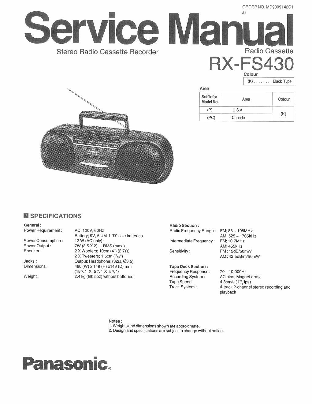
Panasonic rx fs 430 service manual

This is the 13 pages manual for panasonic rx fs 430 service manual.
Read or download the pdf for free. If you want to contribute, please mail your pdfs to info@audioservicemanuals.com.

Page: 1 / 13
left right
panasonic rx fs 430 service manual

Extracted text from panasonic rx fs 430 service manual (Ocr-read)


Page 1

Service M

Stereo Radio Cassette Recorder

ORDER NO. MD930914201

antral

Radio Cassette

RX-FS43O

II SPECIFICATIONS

General :
Power Requirement:

rower Consumption:
Eower Output:
Speaker :

Jacks :
Dimensions:

Weight:

AC; 120V, 60HZ

Battery; 9V, 6 UM«1 "D" size batteries
12 W (AC only)

7w (3.5 X 2) RMS (max.)

2 X Woofers; 100m (4") (2.70)

2 X Tweeters; 1.5cm (As")

Output; Headphone; (329, $3.5)

460 (W) x 149 (H) x149 (D) mm
(18%" x 57/: " X 573")

2.4 kg (5lb 502) without batteries.

Notes 1

Radio Section :

Colour
(K) . . . . . Black Type
Area
Sutfixfor
Model No. Area Colour
(P) u.s.A
(K)
(PC) Canada

Radio Frequency Range :

Intermediate Frequency:

Sensitivity :

Tape Deck Section :
Frequency Response :
Recording System:

Tape Speed :
Track System :

1. Weights and dimensions shown are approximate.
2. Design and specifications are subject to change without notice.

Panasonic.

FM; 88 ~ 108MHz
AM; 525 ~1705kHZ
FM;10.7MHZ

AM; 455kHZ

FM: 12dB/50mW

AM :42.5dB/m/50rnW

70 ~ 10,000Hz

AC bias, Magnet erase

4.8cm/s (17/a ips)

4 playback

Page 2

RX-FS430

ICONTENTS

ISAFETY PRECAUTION,..
oDIAL CHASSIS ASSEMBL
DISASSEMBLY INSTRUCTIONS ................................ 3~ 5 O MECHANISM PARTS LIST...
OTERMINAL GUIDE OF ICS, TRANSISTORS & DIODES ...... 5 0 CABINET PARTS LOCATION
OSCHEMATIC DIAGRAM ......................................
OCIRCUIT BOARD AND WIRING CONNNECTION

I SAF ETY P R ECAUTI O N (This "Safety Precaution" is applied only in USA.) Amhna

VPSHVT

................. 2 o MEASUREMENTS AND ADJUSTMENTS..............,....
2 0 MECHANISM PARTS LOCATION ..............................

.. 7,8 0 REPLACEMENT PARTS LIST..
9.10 O RESISTORS & CAPACITORS.

terminal
Before servicing, unplug the power cord to prevent an electric shock.

When replacing parts ,use only manufacturer's recommended components for safety.

Check the condition of the power cord .Fteplace if wear or damage is evident. EXPOSE"
Atter servicing ,be sure to restore the lead dress, insulation barriers ,insulaiion papers ,shields ,etc. "Em
Before returning the sen/iced equipmentto the customer, be sure to make the following insulation p
resistance test to prevent the customer from being exposed to a shock hazard .

Ohmmeter
Fig. 1

Resistance : SMQ 5.2MQ

OINSU LATION RESISTANCE TEST

1.
2.
3

Unplug the powercord and short the two prongs of the plug with ajumper wire .

Turn on the power switch .

Measure the resistance value with ohmmeter between the jumper AC plug and each exposed metal
cabinet part ,such as screwheads, antenna ,control shafts ,handle brackets , etc , Equipment with antenna

terminals should read between 3M) and 5.2MQ to all exposed parts' .(Fig. 1 ) Equipment without EXPOSSE

antenna terminals should read approximately infinity to all exposed parts . (Fig. 2) "ea'

Note :Some exposed parts may be isolated from the chassis by design. These will read infinity. part

If the measurement is outside the specified limits ,there is a possibility of a shock hazard .The equipment Ohmmeter

Fig. 2

should be repaired and rechecked before it is returned to the customer. R .
esistance = Approx 03

IDIAL CHASSIS ASSEMBLY

Pointer

3. Install the pointer in the direction arrow 0,
follow by 0, then 9.
4. Push the pointer fully to the left.

1 . Screw the tuning knob.
2. Turn the knob lully in an anticlockwise direction.

Screw Screw
(E Dial Chassis

l _n_

l o o . , ,
at) Co 0 5. Install the dial chaSSIs In the
fi I. 00 cabinet and then replace 2
srews.
I:I I: ©
F? m

.. 15,16
.17,18

PAGE

11,12
13
14

19