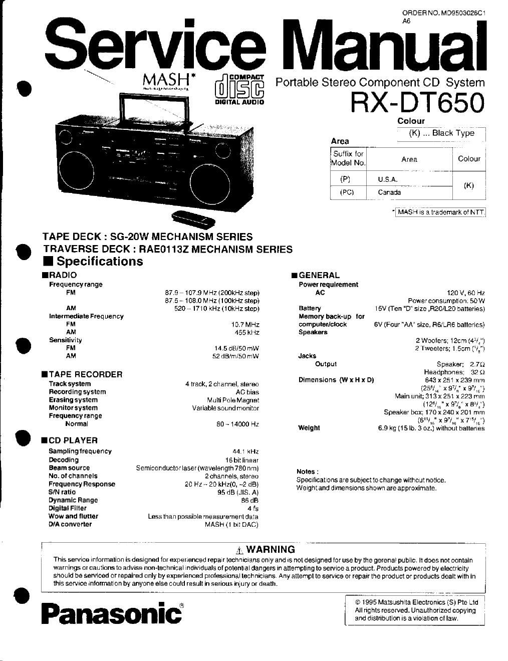
Panasonic rx dt 650 service manual

This is the 51 pages manual for panasonic rx dt 650 service manual.
Read or download the pdf for free. If you want to contribute, please mail your pdfs to info@audioservicemanuals.com.

Page: 1 / 51
left right
panasonic rx dt 650 service manual

Extracted text from panasonic rx dt 650 service manual (Ocr-read)


Page 1

IRA DIO
Frequency range

AM

Intermediate Freq uen cy
FM
AM

Sensitivity
FM

AM

ITAPE RECORDER
Track system
Recording system
Erasing system
Monitor system
Frequency range

Normal

. I CD PL AY ER
Sampling trequency
Decoding
Beam source
No. of channels
Frequency Response
SIN ratio
Dynamic Range
Digital Finer
wow and flutter
D/A converter

7_V._. .. ._.

TAPE DECK : SG-20W MECHANISM SERIES
. TRAVERSE DECK: RAE01132 MECHANISM SERIES
I Specifications

87.9 - 107.9 MHZ (ZOOKHZ step)
875 » 1080 MHz (IOOkHz step)
520 ~1710 kHz (1 OkHz step)

107 MHZ
455 kHz

14.5 dE/SO mW
52 dB/m/50 mW

4 track. 2 channel, stereo
AC bias

Multi Pole Magnet
Variable sound monitor

50 - 14000 Hz

441 kHz

16 bitiinear

Semiconductorlaser (wavelength 780 nrn)
2 channels, stereo

20 HZ - 20 kHziO, ~2 dB)

95 dB (JIS. A)

86 dB

4 ts

Less than possible measurement data
MASH (1 bit DAC)

@COMDACT

BIGIYDAL AUDIO

ORDER NO. M D9503026C1

Service Manual

MASH"

mu u roam-m.» r;

Portable Stereo Component CD System

RX- DT650

Colourfii . 7
(K) Black Type i

Area *7W'
Suffix for i
Model No Area Colour .
(P) U .S.A.
- , (Kl !
(PC) Canada :
. , .
' MASH 1's; trademark o! NTIj
I G E N ERAL
Power requirement
AC 120 V, 60 Hz
Power consumption. 50W
Battery 15V (Ten D" size ,R20/L20 batteries)
Memory back-up Icr
computer/clock 6V (Four "AA" size, RGJLRG batteries)
Speakers
2 Woofers; 12cm (431:)
2 Tweeters; 1.5cn1 (IE")
Jacks
Output Speaker: 275')

Headphones; 32 $1

643 x251x 239 mm

(255/; x 97/5" x 9745")

Main unit; 313 X 251x 223 mm
(1251; x 97/6" x 831")

Speaker box; 170 x240 x 201 mm
(EN/,5" x 945" x 75/15")

Weight 6.9 Kg (15 lb. 3 02.) without batteries

Dimensions (W x H x D)

Notes :
Specrflcatlons are subjectto change without notice.
Weightand dimensrons shown are approximate.

L WARNING-

l This service Intormatlon is designed for experienced repalrtechniCIans only and IS notdesigned for use by the gerenal public. It does not contain
warnings or cautions to advise non-technical individuals of potential dangers In attempting to service a product. Products powered by electricity
should be serviced or repaired only by experienced protessional technicians, Any attempt to service or repair the product or products dealt with in

this sen/Ice information by anyone else could result in serious iniury or death.

Panasonici

© 1995 Matsushita Electronics (5) Pte Ltd _.

All rights reserved. Unauthorized copying
and distributlon IS a violation 0! law.

Page 2

I Contents

SAFETY PRECAUTIONS. ,. ........ 2
PRECAUTION OF LASER DIODE . . 2
OPERATION CHECKS AND MAIN COMPONENT REPLACEMENT 3 ~5
HANDLE PRECAUTIONS FOR TRAVERSE DECK , .. 5
LOCATION OF CONTROLS. . . 8
DIGITALSERVO SYSTEM. .. .

SELF-DIAGNOSTIC DISPLAY FUNCTION
DISPLAY FUNCTION OFAUTOMATICALLYADJUSTED RESULTS 12

Page
TERMINAL GUlDE OF ICs TRANSISTORS AND DIODES 19
WIRING CONNECTION DIAGRAM .. 20
PRINTED CIRCUIT BOARD ..... 21~ 24

SCHEMATIC DIAGRAMS.... .,
MECHANISM PARTS LOCATION (RAAOBOB
MECHANISM PARTSLIST ............. ..
CABINETPARTS LOCATION. , ,. , . ...
REPLACEMENT PARTS LIST..

TROUBLESHOOTING GUIDE
RESISTORS& CAPACITORS ..


MEASUREMENTS ANDADJUSTMENTS......
TERMINAL FUNCTION OF ICS ..... ...

I Safety Precautions (This "Safety Precaution is applied only in U.S.A.)

1. Estate servicing. unplug the poweroord to prevent an electric shock. Antenna

2. when replacing parts. use only manufacturers recommended components forsafety le'mml T

3. Check the condition (it the powercord Replace it wear or damage is evident

4. Alter servicmg the sure to restore the lead dress. insulation barriers ,insulalion papers ,shields .etc . homes a
5. Belore returning the serviced equipment to the customer. be sure to make the fol loWing insulation "W

prm

reststance test to preventthe customertrom being exposed to a shock hazard

@Ohmmeiei
Fig, i

Resistance s 3M1; , S 2M1}

Exposed
metal / , 40%
thmflmi
Fig

. Insulation Resistance Test

1, Unplug the power cord and short the two prongsot the plug With ajumporwire.

2. Turn on the power switch ,

3 Measure the reSIstance value With ohmmeterbetwaen the jumper AC plug and each exposed metal
cabinet part ,such as screwheads, antenna .control shafts handle brackets l etc. Equipment wrth antenna
terminals should read between SMt) and 5 2M) to all exposed parts (Fig, l )Equipmenl Without
antenna terrrti rials should read approrumately infinity to all exposed parts. (Fig, 2 )

Note :Some exposed parts may be Isolated from the chassis by design. These will read inlinity .

4. If the measurement is outside the specilied limits .thera is a possrbility 01a shock hazard The emipment

should be repaired and rechecked before it is returned to the customer.

can

Resrstrmcc ,_ Applax v

I Precaution of Laser Diode

CAUTION: This unit utilizes a class 1 laser. Invi5ible laserradiation isernilted from the optiCal pick up lens.
When the unit is turned on:
I. Do not look directly into the pick up lens.
2 Do not use optical instu rrnents to look at the pick up lens.
3 Do not adiust the preset variable resistoron the pick up lens.
4. Do not disassemble the optical pick up unit.
5 It the optical pick up is replaced, use the manutacturers specified replacement pick up only.
6. Use otcontrol or adjustments or performance of procedures other than those specrlied herein may
rest! in hazardous radiation exposure

What to do when the tape ls entangled i

For Deck 2 ® @ For Deck 1

[ BATTERY SERVICE LIFE


i UM-t tD~5ize) Batteries
Approx. 4% hours of CD playback (EIAJI
. Approx. l2 hours 01 tape recording (ElAJ)
i Approx. Tll hours oi tape playback (EIAJ).

The above battery sen/ice Me is measured
according to the conditions set lonh by

E IAJ (Electronic Industries ASScClaIlOn ol
i . Japan). As the battery servrce lire vanes i
With the method oloperalion and
envirornental conditions use these values
as reference.

When a tape is caught in the pinch roller, etc. , release the tape by turning i
I the pulley on the motor with a scrowdnver in the direclion of arrow