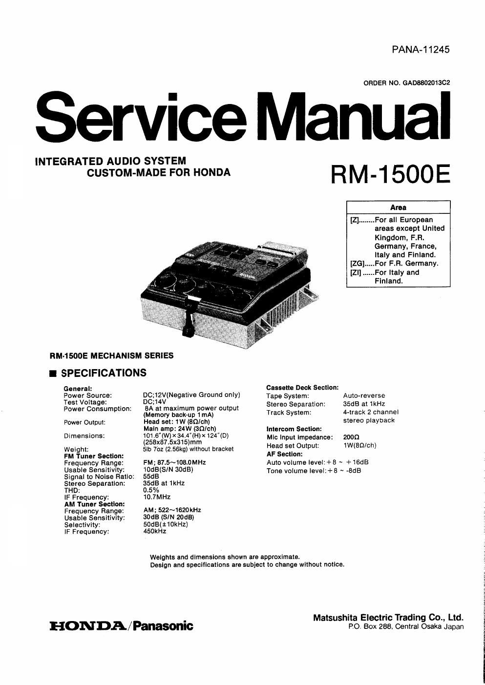
Panasonic rm 1500 e service manual

This is the 26 pages manual for panasonic rm 1500 e service manual.
Read or download the pdf for free. If you want to contribute, please mail your pdfs to info@audioservicemanuals.com.

Page: 1 / 26
left right
panasonic rm 1500 e service manual

Extracted text from panasonic rm 1500 e service manual (Ocr-read)


Page 1

PANA-11245

ORDER NO. GADBBO201302

Service Manual

INTEGRATED AUDIO SYSTEM
CUSTOM-MADE FOR HONDA

RM-1500E MECHANISM semes
I SPECIFICATIONS

General:

Power Source:

Test Voltage:

Power Consumption:

Power Output:
Dimensions:
Weight:

FM Tuner Section:

Frequency Range:
Usable Sensitivity:

Signal to Noise Ratio:

Stereo Separation:
THD:

IF Frequency:

AM Tuner Section:
Frequency Range:
Usable Sensitivity:
Selectivity:

IF Frequency:

DC;12V(Negative Ground only)
DC:14V

8A at maximum power output
(Memory back-up 1mA)

Head set: 1W (SQ/oh)

Main amp: 24W (SO/ch)

101 .6(W) X 34.4"(H)x124(D)
(258x87.5x315)mm

5lb 7oz (2.56kg) without bracket

FM; 87.5~108.0MHZ
10dB(S/N 30dB)
55dB

35:15 at 1kHz

0.5%

10,7MHz

AM; 522~1620 kHz
30dB (SIN 20GB)
SOdBItI OkHz)
450kHz

RM-1500E

Area

[Z] ........ For all European
areas except United
Kingdom, F.R.
Germany, France,
Italy and Finland.

[26] ..... For F.Ft. Germany.

[2|] ...... For ltaly and
Finland.

Cassette Deck Section:
Tape System:

Stereo Separation:
Track System:

Auto-reverse
35dB at 1kHz
4-track 2 channel
stereo playback
Intercom Section:

Mic Input impedance: 2000

Head set Output; twain/ch)

AF Section:

Auto volume ievei:+ 8 - +16dB

Tone volume levei1+8 ~ -8dB

Weights and dimensions shown are approxlmate.
Design and specifications are subject to change without notice.

HONDA/ Panasonic

Matsushita Electric Trading Co., Ltd.
PO. Box 288. Central Osaka Japan

Page 2

CONTENTS

ITEM
Location of Controls and Components
- Audio System Connection .....................
Disassembiy Instructions"
- Schematic Diagram (Main)
0 Schematic Diagram

(Volume/Tone, Power, Connector, Switch Motor/Plunger, Back-UplPlunger) ........................ 10~12
~ Circuit Board and Wiring Connection Diagram
0 Measurements and Adjustments ........................
- ICQ (uPD1714GA929) Each Terminal Function.
Cabinet Parts Location ..
- Mechanism Parts Location ..
- Parts List..


This servlce manual is only applicable to model RM-1500E.
It Is irnapplicable to optional equipment and accessories.