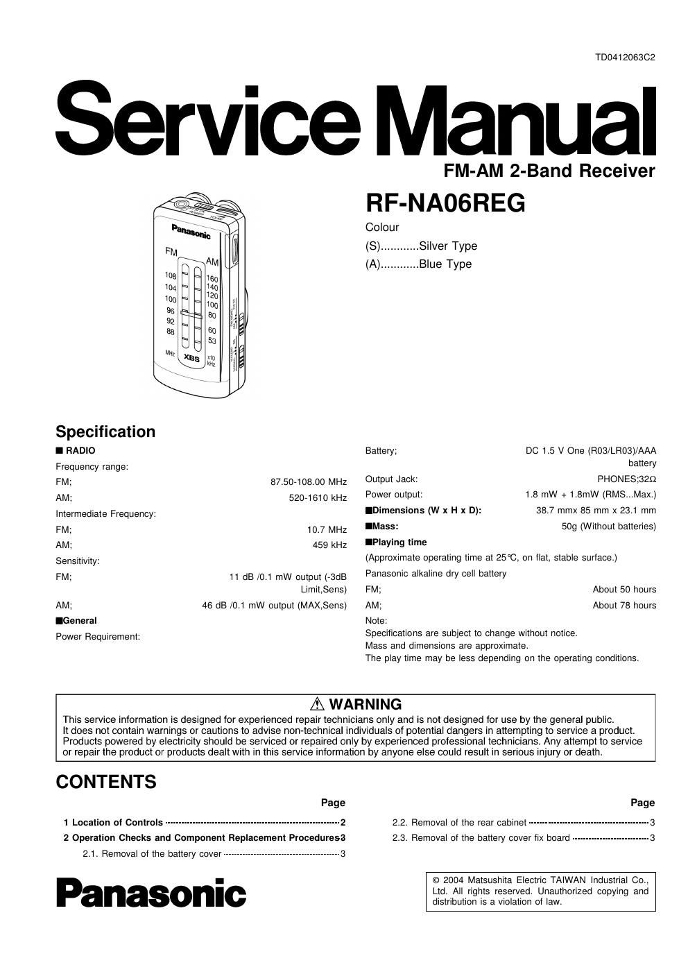
Panasonic rf na 06 reg service manual

This is the 14 pages manual for panasonic rf na 06 reg service manual.
Read or download the pdf for free. If you want to contribute, please mail your pdfs to info@audioservicemanuals.com.

Page: 1 / 14
left right
panasonic rf na 06 reg service manual

Extracted text from panasonic rf na 06 reg service manual (Ocr-read)


Page 1

TD041206302

Service Manual

FM-AM 2-Band Receiver
RF-NAOGREG

Comur
(S) ............ Silver Type
(A) ............ Blue Type
é a
,
7
SpecflmauOn
I RADIO Battery; DC 1.5 V One (R03/LR03)/AAA
Frequency range: battery
FM; 8750408o0 MHz owpm-hck PHONEsozo
AM; 520-1610 kHz Power output: 1.8 mW + 1.8mW (RMS...Max.)
Intermediate Frequency: lDimensions (W x H x D): 38.7 mmx 85 mm x 23.1 mm
FM; 10] MHz IMass: 509 (Without batteries)
AM; 459 kHz lPlaying time
Sensitivity: (Approximate operating time at 25°C, on flat, stable surtace.)
FM; 11 dB /0_1 mW output (-3dB Panasonic alkaline dry cell battery
Limit,Sens) FM; About 50 hours
AM; 46 dB /0.1 mW output (MAX,Sens) AM; About 78 hours
lGeneral Note:
Power Requirement: Specifications are subject to change without notice.
Mass and dimensions are approximate.
The play time may be less depending on the operating conditions.
A WARNING

This service information is designed for experienced repair technicians only and is not designed for use by the general public.

It does not contain warnings or cautions to advise non-technical individuals of potential dangers in attempting to service a product.
Products powered by electricity should be serviced or repaired only by experienced professional technicians Any attempt to service
or repair the product or products dealt with in this service information by anyone else could result in serious injury or death.

CONTENTS

Page

1 Location oi Controls --------------------------------------------------------------- 2
2 Operation Checks and Component Replacement Proceduresa
2.1. Removal of the battery cover ------------------------------------------ 3

Panasonic

Page
2.2. Removal of the rear cabinet ........................................... 3
2.3. Removal of the battery cover fix board ............................ 3

© 2004 Matsushita Electric TAIWAN Industrial Co.,
Ltd. All rights reserved. Unauthorized copying and
distribution is a violation of law.

Page 2

RF-NADGREG

2.4. Removal of the circuit board ass D -------------------------------- 3 4 Schematic Diagram Notes ------------------------------------------------------ 6
2.5. Remov of the tuner knob and middle gear ---------------------- 4 5 Schematic Diagram ------
2.6. Removal of the VC gear and knob


6 Printed Circuit Board Dlagram --

2.7. Remove of the battery room ----- 7 Measurements and Adjustmends

2-8- Removal Of the EP COVSI ---------------------------------------- 4 7.1. Adjustment Instructions ------------------------------------------------ 10
2.9. Removal of the reel unit ------------------------------------------------- 5 72. Adjustment points ........................................................ 11
2.10. Removal of the auto wind knob ------

8 Cabinet Parts Location --------------------------------------------------------- 12

2.11. How to replace the VC gear and dial pointer 9 Packaging .................

3 Type Illustration of ICs, Transistors- 10 Replacement Parts List

1 Location of Controls

POWER
OFF II ON

VOLUME
Retractable earphones

Earphone Jack

TUNING

BAND

,_
w
2
LL

FM MONO

Battery Cover

N.CLEAR
B
.-

NORMAL l X S

TONE