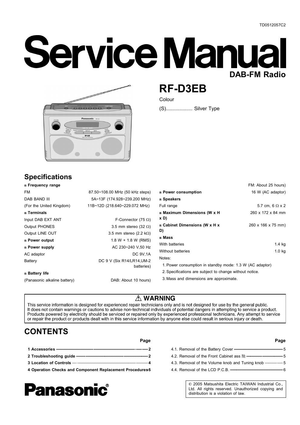
Panasonic rf d 3 eb service manual

This is the 24 pages manual for panasonic rf d 3 eb service manual.
Read or download the pdf for free. If you want to contribute, please mail your pdfs to info@audioservicemanuals.com.

Page: 1 / 24
left right
panasonic rf d 3 eb service manual

Extracted text from panasonic rf d 3 eb service manual (Ocr-read)


Page 1

TD051205702

Service Manual

DAB-FM Radio
RF-D3EB

Colour

(S) ................... Silver Type
Spedficafions
n Frequency range FM: About 25 hours)
FM 87.50~108.00 MHz (50 kHz steps) n Power consumption 16 W (AC adaptor)
DAB BAND ||| 5A~13F (174.928~239.200 MHZ) 11 Speakers
(For the United Kingdom) HB~12D (218.640~229.072 MHz) Full range 5.7 cm, 6 (2 x 2
n Terminals :1 Maximum Dimensions (W x H 260 x 172 x 84 mm
Input DAB EXT ANT F-Connector (75 o) x D)
Output PHONES 35 mm stereo (32 Q) 11 Cabinet Dimensions (W x H x 260 x 166 x 75 mm)

D
Output LINE OUT 3.5 mm stereo (2.2 k9) )
n Power output 1.8 w + 1.8 w (RMS) Mass .
n Power supply Ac 230~24o v,50 Hz with bafler'es_ 14 k9
AC adaptor DC 9V,1A Without batteries 1.0 kg

, Notes:
Battery DC 9 V (Six R14/LR14,UM-2
batteries) 1. Power consumption in standby mode: 1.3 W (AC adaptor)
n Battery life 2.8pecifications are subject to change without notice.
(Panasonic alkaline battery) DAB: About 10 hours) 3* Mass and dimensions are approximate.
A WARNING

This service information is designed for experienced repair technicians only and is not designed for use by the general public

It does not contain warnings or cautions to advise non-technical individuals of potential dangers in attempting to service a product.
Products powered by electricity should be serviced or repaired only by experienced prolessional technicians Any attempt to service
or repair the product or products dealt with in this service information by anyone else could result in serious injury or death.

CONTENTS

1 Accessories --------------

2 Troubleshooting guide
3 Location of Controls-
4 Operation Checks and Component Replacement Proceduress

Panasonic

4.1. Removal of the Battery Cover --------
4.2. Removal of the Front Cabinet ass 551E-
4.3. Removal of the Volume knob and Tuning knob
4.4. Removal of the LCD P.c.B_ ..........................


© 2005 Matsushita Electric TAIWAN Industrial Co.,
Ltd. All rights reserved. Unauthorized copying and
distribution is a violation of law.

Page 2

4.5. Removal of the LCD Ass 51g -------------------------------------------- 6
4.6. Removal of the Speakers ----------------------------------------------- 6
4.7. Removal of the Operation P.C.B.
4.8. Removal of the DAB Unit
4.9. Removal of the Handle"-

4.10. Removal of the Power Button ......................................... 7
4.11. Removal of the ANT P.C,B_ -------------------------------------------- 7
4.12. Removal of the Jack Piece ............................................. 7
4.13. Removal of the Main PCB ---------------------------------------------- 3
4.14. Removal of the Battery PCB (1) and Battery PCB (2) ------ 8
5 Type Illustration of ICs, Transistors and Diodes .................... 9

1 Accessories

- AC adapter
(NOJEEGOOOOO1) ............................................................. 1pc.

@

6 Schematic Diagram Notes ------------------------------------------------------ 9
7 Schematic Diagram ............................................................... 10

8 Printed Circuit Board Diagram
9 Wiring Connection Diagram

1D Adjustments ------------------------
10.1. Tuner Section ---------------------------------------------------- 13
10.2. Check FM Steps .......................................................... 18
11 Cabinet Parts Location ......................................................... 1g
12 Packaging --------------------------------------------------------------------- 20
13 Replacement Parts List --------------------------------------------------------- 21

2 Troubleshooting guide