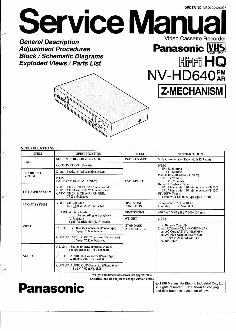
Panasonic nv hd 640 service manual

This is the 60 pages manual for panasonic nv hd 640 service manual.
Read or download the pdf for free. If you want to contribute, please mail your pdfs to info@audioservicemanuals.com.

Page: 1 / 60
left right
panasonic nv hd 640 service manual

Extracted text from panasonic nv hd 640 service manual (Ocr-read)


Page 2

A WARNING

This service information is designed for experienced repair technicians only and is not designed for use by the general public. It does
not contain warnings or cautions to advise non-technical individuals of potential dangers in attempting to service a product.

Products powered by electricity should be serviced or repaired only by experienced professional technicians. Any attempt to service or
repair the product or products dealt with in this service information by anyone else could result in serious injury or death.

INTRODUCflON

This service manual contains technical information which will allow service personnels to understand and service this model.
Section 1 presents you with technical know how for actual servicing and general information of features and controls, enabling
you to become familiar with each function.

Section 2 presents to you mechanical and electrical adjustment information as well disassembly and replacement procedures.
in the case of very common information relating to other models like mechanical adjustments, please refer to the appropriate
service manual.

Section 3 contains block diagrams which provides you with information for checking and understanding each circuit. Schematic
diagrams which give you detailed information such as waveforms, voltage data, function etc.

Section 4 contains exploded views and parts list.

Please place orders using the parts list and not the drawing reference numbers.

If the circuit is changed or modified, this information will be followed by supplementary service manual to be filed with original

sen/ice manual.
CONTENTS

SECTION 1 GENERAL DESCRIPTIONS. 1-1
1- 1. SERVICE INFORMATION ............ 1-1
1 -1- 1. MICROPROCESSOR REST AND INITIALIZATION 1-1
1-1-2. CHECKING OF MAIN C B.A 1-1
1-1-3. REMOVAL OF CASSETTE TAPE . 1-1
1-1-4. CYLINDER UNIT REPLACEMENT . 1-2
A. CYLINDER UNIT REPLACEMENT 1-2
B. UPPER CYLINDER DISASSEMBLY. . 1-2
G. UPPER CYLINDER ASSEMBLY" 1-2
1-2. SELF- TEST & SERVICE INFORMATION DISPLAY 1-3
1-6. CAUTION DURING AUTO TUNING ............... 1-3
1-4. OPERATING INSTRUCTIONS (NV-HD64OPM) 1-4

SECTION 2ADJU5TMENT PROCEDURES
2-1. DISASSEMBLY METHOD ....................
2-2. MECHANICAL ADJUSTMENT PROCEDURES
2-3. ELECTRICAL ADJUSTMENT PROCEDURES .

2-3-1. TEST EQUIPMENT .............
2-3-2. PG SHIFI'ER ADJUSTMENT .

SECTION SBLOCK DIAGRAMS & SCHEMATIC DIAGRAMS.
3-1. ABBREVIATIONS & Input Output chart for ICGOO1
3-2. AUDIO SECTION BLOCK DIAGRAM ....................
3-3. SYSTEM CONTROL 8 SERVO/TIMER SECTION BLOCK DIAGRAM
3-4. VIDEO SECTION BLOCK DIAGRAM
3-5 POWER SCHEMATIC DIAGRAM
3-6. SYSTEM CONTROL & SERVO/TIMER SECTION IN MAIN SCHEMATIC DIAGRAM.
3-7. VIDEO SECTION IN MAIN SCHEMATIC DIAGRAM
3- 8. AUDIO SECTION IN MAIN SCHEMATIC DIAGRAM
3- 9. CAPSTAN DRIVE UNIT SCHEMATIC DIAGRAM...
3-10 TV DEMODULATOR PACK SCHEMATIC DIAGRAM
3-11. CYLINDER CONNECTION SCHEMATIC DIAGRAM
3-12. CYLINDER CONNECTION C.B.A. (VEPOOZSSA)
3-13. TV DEMODULATOR PACK C.B.A. (VEP07995A)
3-14. POWER C.B.A. (VEP01842A) ..............................
3-15. MAIN C.B.A.(VEPOBC8BM:NV-HDB4OPM) (VEPOGCBBL. V-HD64OAR)

SECTION 4 EXPLODED VIEWS & PARTS LIST ................................
4-1. EXPLODED VIEW MECHANICAL REPLACEMENT PARTS LIST

1. CHASSIS PARTS SECTION.

2. CASING PARTS SECTION

3. PACKING PARTS SECTION

4-2. ELECTRICAL REPLACEMENT PARTS LIST