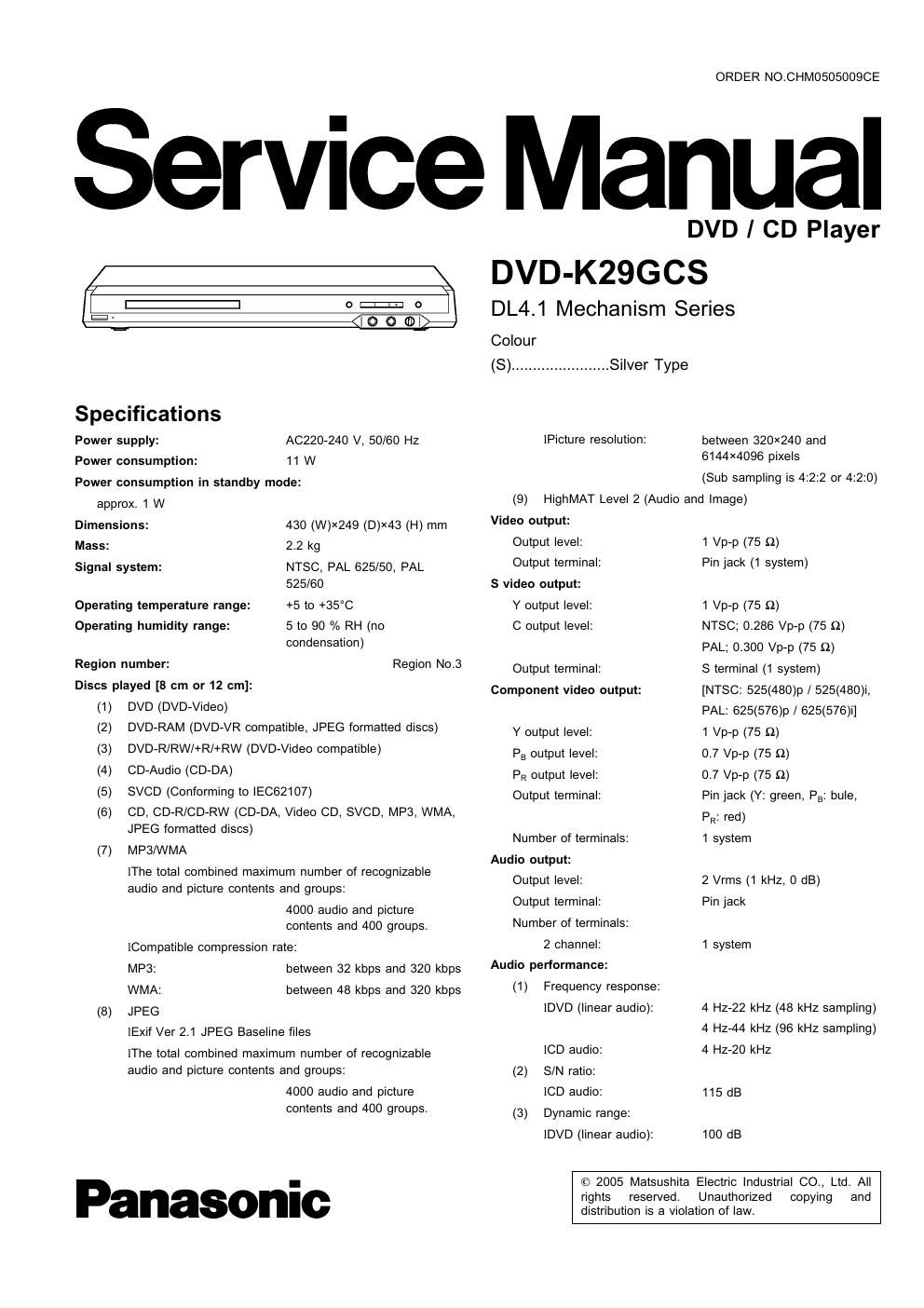
Panasonic dvd k 29 gcs service manual

This is the 64 pages manual for panasonic dvd k 29 gcs service manual.
Read or download the pdf for free. If you want to contribute, please mail your pdfs to info@audioservicemanuals.com.

Page: 1 / 64
left right
panasonic dvd k 29 gcs service manual

Extracted text from panasonic dvd k 29 gcs service manual (Ocr-read)


Page 2

DVD-KZSGCS

lCD audio: 98 dB
(4) Total harmonic distortion:
[CD audio: 0.0025 /0
Digital audio output:
Coaxial digital output: Pin jack
Pickup
Wave length: 662 nm/785 rim

Laser power: CLASS 2/CLASS 3A

Note:
Specifications are subject to change without notice.
Mass and dimensions are approximate.
Solder:

This model uses lead free solder (PbF).

Manutauured under license Irom Dolby Laboratories. Dolby" and the doubterD
symbol are trademarks OI Dolby Laboratories

DTS" and DTS 2.0 1 Digital Out" are trademarie 01 Digital Theater Systems, Inc.

This product incorporates copyright protection technology that is proreaed by method
claims 01 certain U.S. patents and other intellectual property rights owned by
Macrovlsion Corporation and other rights owners, Use at this copyright protection
technology mud be authorized by Macrovlslon Corporation, and Is Intended tor home
and other limited viewing uses only unless otherwise authorized by Macrovision
Corporation. Reverse engineering or disassembly is prohibited.

MPEG Layer73 audio deoodingtechnology licensed trom Fraunhoter IIS and Thomson
multimedia.

HighMATrM and the HighMAT logo are either trademarks or
registered trademarks oi Microsott Corporation in the United

States and/or other countries, 2..
Windows Media, and the Windows logo are trademarks,
or registered trademarls of Microsoft Corporation in the
United States and/or other countries.

- Mm row
WMA is a compression lormat developed by Microsott .._ mtg
Corporation. It achieves the same sound qualfly as MP3

with a tile size that is smaller than that oi MP3.

AWARNING

This service information is designed for experienced repair technicians only and is not designed for use by the general public.

It does not contain warnings or cautions to advise non-technical individuals of potential dangers in attempting to service a product.
Products powered by electricity should be serviced or repaired only by experienced protessional technicians. Any attempt to service
or repair the product or products dealt with in this service information by anyone else could result in serious injury or death.

CONTENTS

Page
1 SAFETY PRECAUTIONS --------------------------------------------------------- 4
1.1. GENERAL GUIDELINES ------------------------------------------------ 4

2 PREVENTION OF ELECTRO STATIC DISCHARGE (ESD) TO

ELECTROSTATICALLY SENSITIVE (ES) DEVICES
3 Precaution of Laser Diode
4 About lead free solder (PbF)
5 PREVENTION OF STATIC ELECTRICITY DISCHARGE ------------ 6

5.1. Grounding for electrostatic breakdown prevention ............ 5


5.2. Handling Precautions for Traverse Unit (Optical Pickup) --6
6 DISASSEMBLING THE CASING AND CHECKING P.C.B.S ------ 7
6.1. Disassembly Procedure -----------
6.2. Casing Parts and P.C.B. Positions ---------------------------------- 7
6.3. Top Panel-
6.4. Front Panel --
6.5. Mic P.C.B. and Operation P.C.B.

6.6. Module P.C.B. ...................................................... g
6.7. Mechanism Unit ------------------------------------------------------------- g
6.8. Rear Panel -------------------------------------------------------------------- g
6.9. Mother P.C.B. and Power sw P.C.B. ............................. g
6.10. Service Position ----------------------------------------------------------- 10

7 ASSEMBLING AND DISASSEMBLING THE MECHANISM UNIT

7.1. Disassembly Procedure

7.2. Traverse Unit --------------
7.3. Tray ----------------------------------------------------------------------------- 12
7.4. Loading section ------------------------------------------------------------ 13
7.5. Loading motor P.C.B. ................................................... 14

Page
7.6. Optical Pickup Unit ------------------------------------------------------- 15
7.7. Traverse Motor ---------------------------------------------------- 17

8 Self-Diagnosis Function and Service Modes


8.1. Optical Pickup Breakdown Diagnosis
8.2. Service Mode Table 1 -
8.3. DVD Self Diagnostic Function-Error Code

8.4. Last Error Code saved during No PLAY ....................... 21
8.5. Service mode table 2 ................................................... 22
8.6. Sales demonstration lock function ................................. 24
8.7. Handling After Completing Repairs ............................... 24
9 Service Precautions .............................................................. 25
9-1- Recovery after the dvd player is repaired ---------------------- 25

9.2. Firmware version-up of the DVD player
10 ADJUSTMENT PROCEDURES
10.1. Service Tools and Equipmen

10.2. important points in adjustment ...................................... 25
10.3. Storing and Handling Test Discs ................................... 25
10.4. Optical adjustment ------------------------------------------------------- 27
11 Abbreviations ------------------------------------------------------------------------ 29
12 VOLTAGE CHART ................................................................. 31
12.1. MOTHER P.C.B. .......................................................... 31
12.2. MODULE P.C.B.
12.3. MIC P.C.B
13 BLOCK DIAGRAM-
131. OVERALL BLOCK DIAGRAM ....................................... 35
13.2. POWER SUPPLY BLOCK DIAGRAM ........................... 35
13.3. SERVO BLOCK DIAGRAM .......................................... 37