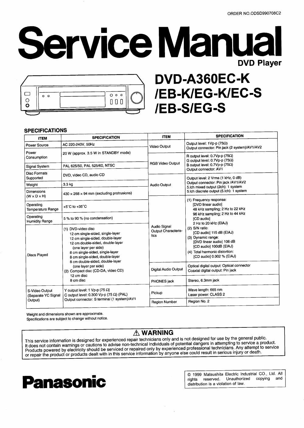
Panasonic dvd a 360 service manual

This is the 93 pages manual for panasonic dvd a 360 service manual.
Read or download the pdf for free. If you want to contribute, please mail your pdfs to info@audioservicemanuals.com.

Page: 1 / 93
left right
panasonic dvd a 360 service manual

Extracted text from panasonic dvd a 360 service manual (Ocr-read)


Page 1

ORDER N0.0DSD99070802

rvice Manual

DVD Player

\ DVD-A360EC-K

D on :: lEB-KlEG-KIEC-S
0
° W I EB SIEG S
- -
V
SPECIFICATIONS
ITEM SPECIFICATION ITEM SPECIFICATION
Po e Sour AC 220-240V. 50H: 1 _
w r so Video Output gztpul level lep .(750)
pm connector. Pin jack (2 system)/AVl/AV2

POW _ 20 w (approx. 3.5 w in STANDBY mode)
Consumption Fl output level: 0.7Vp-p (75m

. G output level: 0.7Vp»p (750)
Signal System PAL 625/50. PAL 525/60, NTSC 53 V'de" 0mm B output level: 07Vp-p (75m

Output connector: AW
35" Fag DVD, video on, audio co
9° Output level: 2 Vrms (1 kHz, 0 d8)
Weight 3.3 kg A dl O t Output connector: Pin jack lAVr/AV2
Dimensions u o u on 5.lch mixed output (Zen): 1 system
(w x D x H) 430 x 268 x 94 mm (excluding protrusions) 5-lch discrete output (5-lchl: 1 system
(1) Frequency response:

gperatln? Ft +5- C to +351; [DVD linear audio]

9" '9 99 4a kHl sampling; 2 Hz to 22 kHz
Operating a . 96 kHz sampling; 2 H1 to 44 kHz
Humidity Range 5 lo to 90 /e (no condensation) [CD audio]

, 2 Hz to 20 kHz (EIAJ)
(1) DVD-video disc Audl" 5W . (2) S/N ratio:
12 cm single-sided, single 12 cm single-sided. double-layer CS (3) Dynamic range:
12 cm double-sided. double-layer [DVD linear audio] 106 dB
(one layer per side) [CD audio] 100GB (EIAJ)
Discs Played 3 cm single-sided. singlelaver (4) Total harmonic dislonion:
8 cm single-Sided, double-layer [CD audio] 0002 % (EIAJ)
8 cm double-sided, double-layer
(one We] per Side) , _ _ Optical digital output: Optical connector
(2) Compact 5" (CD-DA, V'de" CD) DigitalAudio Output Coaxial digital output: Pin jack
12 cm disc
8 cm 1' PHONES Jack Stereo, 6.3mm lack
S-Video Output V output level: 1 Vp

(Separate vc Signal 0 output level: 0.300 Wm) (75 :1) (PAL) P'ckup Lass, power: CLASS 2
Output) Output connector: 5 terminal (1 system/AW
Region Number Region No. 2
Weight and dimensions shown are approximate.
Specifications are subject to change without notice.
A WAR N i NG

This service information is designed for experienced repair technicians only and is not designed for use by the general public.

It does not contain warnings or cautions to advise non-technical individuals of potential dangers in attempting to service a product.
Products powered by electricity should be serviced or repaired only by experienced prolessional technicians. Any attempt to service
or repair the product or products dealt with in this service information by anyone else could result in serious injury or death.

© 1999 Matsushita Electric Industrial 00., Ltd. All

-
n I rights reserved. Unauthorized copying and
distribution is a violation of law.

Page 2

DVD-ASSDEC-K I /EB~KIEG-KIEC-S I lEB-leG-S

CONTENTS

1 SAFETY PRECAUTIONS ------------------
1.1. GENERAL GUIDELINES --------

2 PREVENTION OF ELECTRO STATICDISCHARGE (ESD) T0
ELECTROSTATICALLY SENSITIVE (ES) DEVICES ------------------ 4
3 PRECAUTION OF LASER DIODE ---------------------------
4 HANDLING PRECAUTIONS FOR TRAVERSE DECK-
4.1. Handling of optical pickup ------------------------------
4.2. Grounding for electrostatic breakdown prevention ------------ 5
5 Optical Pickup Self-Diagnosis and Replacement Procedure-6
6 Self-Diagnosis Function and Service Modes
6.1. Service Mode Table -------------
6.2. Self-Diagnosis Function (UHF Display)~

6.3. Examples of Repairs Using Error Codes -------------------------- 8
6.4. Sales Demonstration Lock Function --------------------------------- 8
7 Service Tools and Equipment -------------
7.1. Service Tools and Equipment Tabl
7.2. Storing and Handling Test Discs-
8 General Description ----------------------------------------------------------------- 10

8.1. Operating Instructions -------------------------------------------------- 10

9 Assembling and Disassembling the Casing and Checking
C.B.A.s -----------------------------------------------
9.1. Disassembly Procedure -----------
9-2- Casing Parts and C.B.A. Positions .................................. 27
9.3. Service Positions ------------------------------------------------------------ 27

9.4. Disassembling the Top Cove

9.5. Disassembling the Tray ----- 28
9.6. Disassembling the Front Panel- 29
9.7. Disassembling the Loading Base Unit ---------------------------- 29
9.8. Checking the Module C.B.A. ------------------------------------------- 29

9.9. Disassembling the Rear Panel -----
9.10. Checking the Power Supply C.B.A.~
9.11. Checking the Mother C.B.A. -----
9,12. Checking the Front Switch C.B.A. ----------------------------------- 31
9.13. Checking the Headphone Volume and Power Switch

C.B.A.
9.14. Checking the Headphone Jack C.B.A.
10 Service Precautions ------------------------------
10.1. Initializing the DVD Player ---------------------------------------------- 32
10,2. Handling After Completing Repairs --------------------------------- 32

11 Assembling and Disassembling the Optical Pickup
(Mechanical Parts) ----------------
11.1. Handling the Optical Pickup --------------------------
11.2. Disassembly Procedure -------------------------------------------------- 33
11.3. Lubricating the Loading Base Unit
11.4. Static Electricity Countermeasures
11.5. Disassembling the Clamp Base Unit
11.6. Disassembling the Clamper Weight. Clamper Yoke,
Magnet and Clampar -----------------

11.7. Disassembling the Traverse Unit ----------------------------------- 36
11.8. Disassembling the Stepping Motor Unit
11.9. Disassembling the Optical Pickup Unit-

11.10. Disassembling the Nut Unit -------------------
11.11. Disassembling the Sub-Shaft Preload Spring ----------------- 38
11.12. Assembling the Optical Pickup-
11.13. Disassembling the Spindle Motor Unit

1114. Optical Pickup Tilt Adjustment ........................................ 40
-15 Disassembling the Intermediate Chassis ------------------------ 42
11.16. Disassembling the Vertical cam and Drive gear -------------- 42

11.17. Disassembling the Pulley Gear and Deceleration Gear-~42
11.18. Disassembling the Mechanism Loading C.B.A. -------
11.19. Lubricating the Optical Pickup and Peripheral Parts ------- 43
12 Electrical Adjustment -----

12.1. Video Output (Luminance Signal) Adjustment ---------------- 44
12.2. Video Output (Chrominance Signal) Adjustment --
12.3. Video Component Signal (CB) Output Adjustmen
13 Abbreviations ------------------------------------------------------------
14 VOLTAGE CHART --------------------------------------------------------------------- 48
14.1. POWER SUPPLY C.B.A.
14.2. MODULE C.B.A.
14.3. MOTHER C.B.A.
14.4. SCART C.B.A. --------------------------------------------------------
14.5. HEADPHONE JACK C.B.A. -------------------------------------------- 56
14.6. HEADPHONE VOLUME C.B.A
15 BLOCK DIAGRAM ---------------
15.1. OVERALL BLOCK DIAGRAM
15.2. SERVO BLOCK DIAGRAM --------------------------------------------- 58
15.3. VIDEO BLOCK DIAGRAM ---------------------------------------------- 59
15.4. AUDIO BLOCK DIAGRAM
16 SCHEMATIC DIAGRAM -------
16.1. INTERCONNECTION SCHEMATIC DIAGRAM~


16.2, POWER SUPPLY SCHEMATIC DIAGRAM -------------------- 62
16.3. ADSC SECTION (MODULE C.B.A. (1/7)) SCHEMATIC
DIAGRAM 1- -------------------------------------------------------- 63
16.4. AV DECORDER SECTION (MODULE C.B.A. (2/7))
SCHEMATIC DIAGRAM --------------------------------------- 64
16.5. VIDEO D/A CONVERTER SECTION (MODULE C.B.A.
(3/7)) SCHEMATIC DIAGRAM ------------------------------ ---65
16.6. FEP SECTION (MODULE c. (4/7)) SCHEMATIC
DIAGRAM ------------------------- - -66
16.7. CPU SECTION (MODULE 0 BA. (5/7)) SCHEMATIC
DIAGRAM -------------------------------------------------------------- 67
16.8. AUDIO SECTION (MODULE C.B.A. (6/7)) SCHEMATIC
DIAGRAM -------------------------------------------------------- 68
16.9. ODC SECTION (MODULE C.B.A. (7(7)) SCHEMATIC
DIAGRAM ------------------------------------------------------------- 69
16.10. VIDEO OUT SECTION (MOTHER C.B.A. (1/3))
SCHEMATIC DIAGRAM ------------------------------------------------- 70
16.11. AUDIO OUT SECTION (MOTHER C.B.A. (2/3))
SCHEMATIC DIAGRAM ----------------- 71
16.12. OPERATION SECTION (MOTHER C.B.A. (3/3))
SCHEMATIC DIAGRAM --------------------------------------- 72
16.13. SCART SCHEMATIC DIAGRAM ------------------------------------ 73