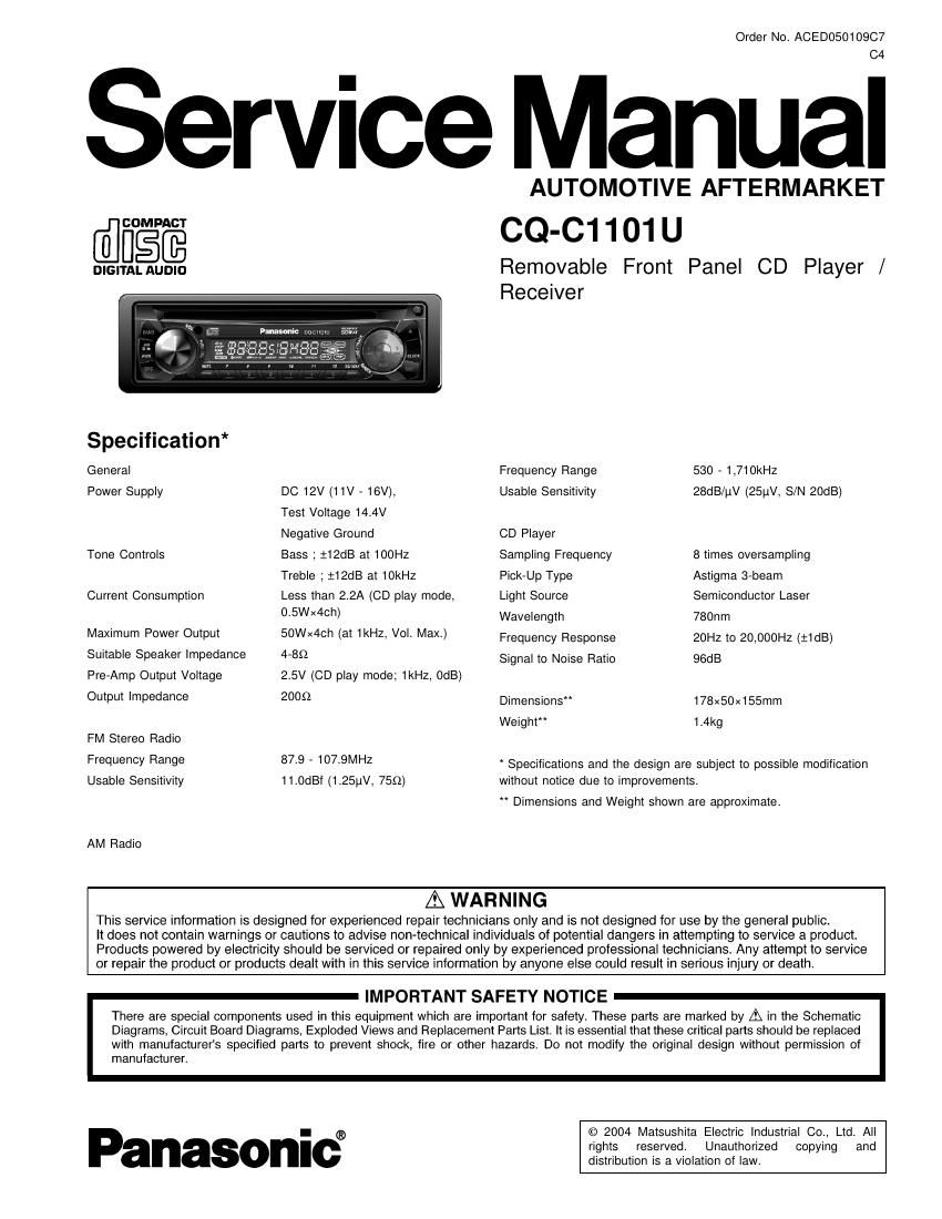
Panasonic cq c1101

This is the 30 pages manual for panasonic cq c1101.
Read or download the pdf for free. If you want to contribute, please mail your pdfs to info@audioservicemanuals.com.

Page: 1 / 30
left right
panasonic cq c1101

Extracted text from panasonic cq c1101 (Ocr-read)


Page 1

Order No. ACED05010907

Service Manual

AUTOMOTIVE AFTERMARKET
@figfi CQ-C1101 U

DIGITALAUDID Removable Front Panel CD Player /
Receiver

Specification*

General Frequency Range 530 - 1,710kHz

Power Supply DC 12V (11V - 16V), Usable Sensitivity 28dB/uV (25uV, S/N 20dB)
Test Voltage 14.4V
Negative Ground CD Player

Tone Controls Bass ; :12dB at 100Hz Sampling Frequency 8 times oversampling
Treble ; :12dB at 10kHz Pick-Up Type Astigma 3-beam

Current Consumption Less than 2.2A (CD play mode, Light Source Semiconductor Laser
0-5WX4Ch) Wavelength 780nm

Maximum Power Output 50Wx4ch (at 1kHz, Vol. Max.) Frequency Response 20Hz to 20,000HZ (:1dB)

Suitable Speaker Impedance 4-85) Signal to Noise Ratio 96dB

Pre-Amp Output Voltage 2.5V (CD play mode; 1kHz, OdB)

0tht 'mpedance 2009 Dimensions" 178x50x155mm

Weight 1.4kg

FM Stereo Radio

Frequency Range 87-9 ' 107-9MHZ Specifications and the design are subject to possible modilication

Usable Sensitivity 11.0dBf (1 .25uV, 755)) without notice due to improvements.

" Dimensions and Weight shown are approximate.

AM Radio

A WARNING

This service information is designed for experienced repair technicians only and is not designed for use by the general public.

It does not contain warnings or cautions to advise non-technical individuals of potential dangers in attempting to service a product.
Products powered by electricity should be serviced or repaired only by experienced professional technicians. Any attempt to service
or repair the product or products dealt with in this service information by anyone else could result in serious injury or death.

IMPORTANT SAFETY NOTICE

There are special components used in this equipment which are important for safety. These parts are marked by A in the Schematic
Diagrams, Circuit Board Diagrams, Exploded Views and Replacement Parts List. It is essential that these critical pans should be replaced
with manufacturers specilied parts to prevent shock, fire or other hazards. Do not modify the original design without permission of

manufacturer.

© 2004 Matsushita Electric Industrial Co., Ltd. All

- ®
P n I rights reserved. Unauthorized copying and
distribution is a violation of law.

Page 2

CONTENTS

Page
1 ABOUT LEAD FREE SOLDER (PbF) ....................................... 2
2 FEATUERS ------------
3 LASER PRODUCTS
4 REPLACEING THE FUSE -------------------------------------------------------- 2
5 MAINTENANCE
6 NOTES ------------
7 DIMENSIONS --------------------------------------------------------------------------- 3

8 WIRING CONNECTION-
9 BLOCK DIAGRAM -----
1U TERMINALS DESCRIPTION ..................................................... 6

1 ABOUT LEAD FREE
SOLDER (PbF)

Distinction of PbF PCB:

PCBs (manufactured) using lead free solder will have a PbF
stamp on the PCB.

Caution :

~ Pb free solder has a higher melting point than standard
solder; Typically the melting point is 50 - 70°F (30 »
40°C) higher. Please use a soldering iron with
temperature control and adjust it to 700 t 20°F (370 :
10°C). In case of using high temperature soldering iron.
please be careful not to heat too long,

~ Pb tree solder will tend to splash when heated too high
(about 1100°F/600C)

~This lead free solder will be used for the products after
serial No. 1,000,001.

2 FEATUERS

- Remote Control.

- 18-FM, 6»AM presets with preset scan
- Digital servo for reliable CD playback.
- Removable face plate.

Page
11 PACKAGE AND Ic BLOCK DIAGRAM ..................................... a
12 REPLACEMENT PARTS LIST ---11
13 EXPLODED VIEW (Unit) -------- ".15

14 CD PLAYER MECHANICAL PARTS LIST ............................... 17
15 EXPLODED VIEW (CD Deck)- ---13
16 PACKING PARTS LIST -------
17 WIRING DIAGRAM ................................................................. 20
18 SCHEMATIC DIAGRAM>1
19 SCHEMATIC DIAGRAMvZ
20 SCHEMATIC DIAGRAM for printing with Letter size ------------ 29

3 LASER PRODUCTS

CAUTION:
This product utilizes a laser diode with the unit turned "on",
laser radiation is emitted from the pickup lens.
Laser radiation from the pickup lens is safety level, but be
sure the followings:
1. Do not disassemble the optical pickup unit, since
radiation from exposed laser diode is dangerous.
2, Do not adjust the variable resistor on the pickup unit.
It was already adjusted.
3. Do not look at the focus lens using optical instruments.
4. Recommend not to look at pickup lens for a long time.

DANGER! Invisible laser radiation when open.
Avoid direct exposure to beam.

Deck Ass'y (Upper Side)

Caution

This Product utilizes a laser.

Use of controls or adjustments or performance 01
procedures other than those specified herein may
result in hazardous radiation exposure.

4 REPLACEING THE FUSE

Use fuses of the same specified rating (15A). Using different
substitutes or fuses with higher ratings, or connecting the
product directly without a fuse, could cause fire or damage to
the stereo unit.