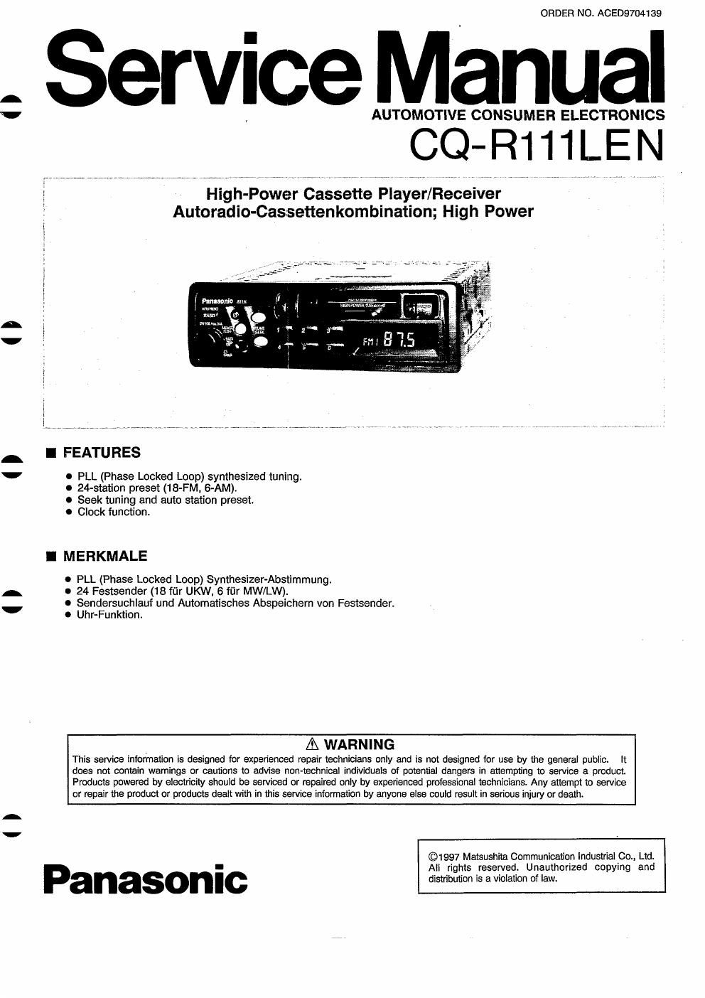
Panasonic cq r 111 len service manual

This is the 28 pages manual for panasonic cq r 111 len service manual.
Read or download the pdf for free. If you want to contribute, please mail your pdfs to info@audioservicemanuals.com.

Page: 1 / 28
left right
panasonic cq r 111 len service manual

Extracted text from panasonic cq r 111 len service manual (Ocr-read)


Page 2

CQ-R111LEN I

CONTENTS
Page

REPLACEMENT FUSE ...................... 1
MAINTENANCE ........................... 1
RADIO ALIGNMENT ....................... 1
ALIGNMENT JIG .......................... 1
DIMENSIONS ............................. 1
SPECIFICATIONS ......................... 2
< OPERATING INSTRUCTIONS >

Power and Sound Controls ................. 3

Radio Basics ......................... 3, 4

Cassette Tape Play Basics ................. 4

Clock Basics ............................ 5

Installation Guide ......................
Electrical Connection
Speaker Connections
BLOCK DIAGRAM ......
SCHEMATIC DIAGRAM
WIRING DIAGRAM

TERMINALS DESCRIPTION ................ 17
PACKAGE AND IC BLOCK DIAGRAM ........ 18
REPLACEMENT PARTS LIST ..... 19~22, 25~27
EXPLODED VIEW (Unit) .................... 23
EXPLODED VIEW (Tape Deck) 24

FUSE
Be sure to use a fuse of the specified rating (10A)
when replacing a blown fuse. Fuses with higher
capacity ratings, use of any substitute, or connection
without a fuse may result in a fire hazard or damage to
the unit.

MAINTENANCE

To clean the exterior of this unit, use a soft cloth to
wipe the surface. Do not use benzine, thinner, or any
other type of solvents.

RADIO ALIGNMENT
Do not align the AM and FM package blocks. When

the package block is necessary, it will be supplied
already aligned at the factory.

ALIGNMENT JIG
c DOLBY NR ALIGNMENT ;
Test Tape: RFK20038

INHALTSUERZEICHNIS
Seite
SICHERUNG ............................... 1
PFLEGE ................................... 1
AUDIO ABGLEICH ........................... 1
ABGLEICH-SCHABLONE ...................... 1
ABMESSUNGEN ............................ 1
TECHNISCHE DATEN ........................ 2
< BEDIENUNG SANLEITUNG >
Stromversorgung und Klangregler ............. 8
Rundfunkempfang ......................... 9
Cassettenwiedergabe ...................... 10
GrundIagen fiir die Gedienung der Uhr ......... 10
Einbau ............................... 11, 12
Elektrischer AnschluB ...................... 13
AnschluB der Lautsprecher . . 13
BLOCK DIAGRAM .......... 14
SCHALTBILT ............................ 15
VERDRAHTUNG ........................... 16
KLEMMENBESCHREIBUNG .................. 17
PACKEN UND IC BLOCK DIAGRAM ............ 18
ERSATZIEILLISTE ............... 19 ~22, 25 ~27
AUFGELOTE DARSTELLUNGS
(GANZES GERAT) .......................... 23
AUFGELOTE DARSTELLUNGS
(TONBAND GERAT) ........................ 24

SICHERUNG

Als Ersatz iiir eine durchgebrannte Sicherung
unbedingt eine Sicherung mit dem vorgeschriebenen
Nennwert (10A) verwenden. Durch den Gebrauch von
Sicherungen mit hdheren Nennwerten, vcn
Sicherungsersatzteilen oder durch den AnschluB ohne
Gebrauch einer Sicherung kann ein Brand oder
Ger'ateschaden verursacht werden.

PFLEGE

Zur Reinigung das aussere des Gerates mit einem
weichen Tuch abwischen. Auf keinen Fall Benzin,
Verdijnner oder irgendein anderes Losemittel
verwenden.

RADIO ABGLEICH

Niemals LW/MW und UKW abgleichen. Vom Werk
gelieferete Austauschplatinen sind bereits abgestimmt.

ABGLEICH-SCHABLONE
I DOLBY NR ABGLEICH :
Testband : RFKZOOSS

DIMENSIONS / ABMESSUNGEN

II

II

I I