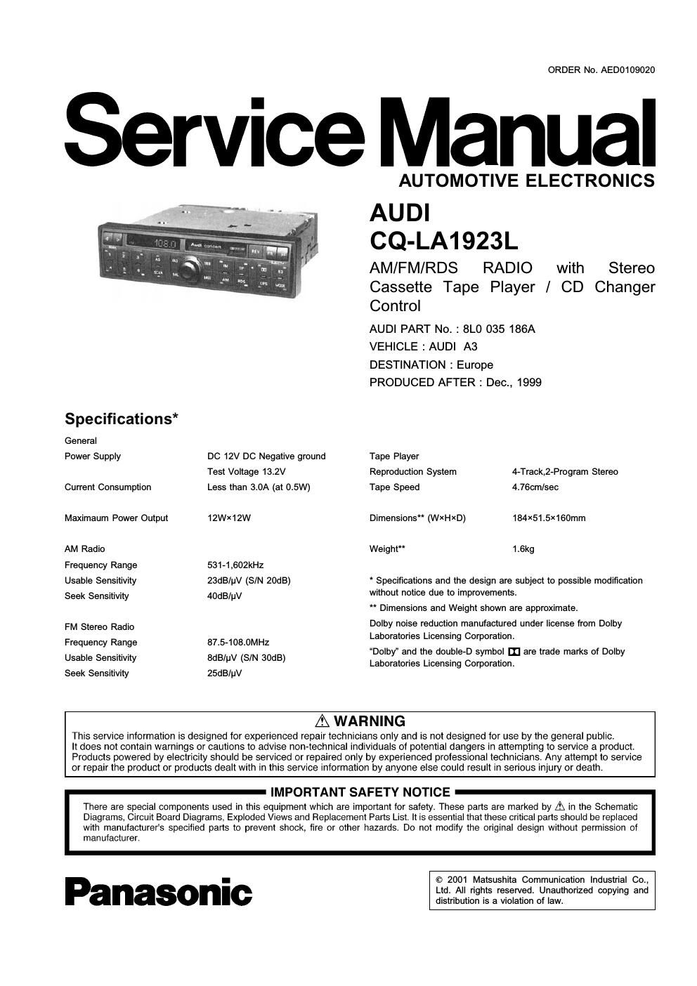
Panasonic cq la 1923 l service manual

This is the 23 pages manual for panasonic cq la 1923 l service manual.
Read or download the pdf for free. If you want to contribute, please mail your pdfs to info@audioservicemanuals.com.

Page: 1 / 23
left right
panasonic cq la 1923 l service manual

Extracted text from panasonic cq la 1923 l service manual (Ocr-read)


Page 1

ORDER No. AED0109020

Service Manual

Specifications*
General

Power Supply
Current Consumption
Maximaum Power Output

AM Radio
Frequency Range
Usable Sensitivity
Seek Sensitivity

FM Stereo Radio
Frequency Range
Usable Sensitivity
Seek Sensitivity

DC 12V DC Negative ground
Test Voltage 13.2V
Less than 3.0A (at 0.5W)

12WX12W

531-1,602kHz
23dB/pV (S/N 20dB)
40dB/pV

87.5-108.0MHZ
8dB/uV (S/N 30dB)
25dB/pV

AUTOMOTIVE ELECTRONICS

AUDI
CQ-LA1923L

AM/FM/RDS RADIO with Stereo
Cassette Tape Player / CD Changer
Control

AUDI PART No. : 8L0 035 186A

VEHICLEzAUDI A3

DESTINATION : Europe

PRODUCED AFTER: Dec., 1999

Tape Player

Reproduction System 4~Track,2~Program Stereo
Tape Speed 4.76cm/sec

Dimensions" (WXHXD) 184X51.5X160mm
Weight" 1.6kg

* Specifications and the design are subject to possible modification
without notice due to improvements.

" Dimensions and Weight shown are approximate.

Dolby noise reduction manufactured under license from Dolby
Laboratories Licensing Corporation.

Dolby" and the double~D symbol II] are trade marks of Dolby
Laboratories Licensing Corporation.

A WARNING

This service information is designed for experienced repair technicians only and is not designed for use by the general public,

It does not contain warnings or cautions to advise non-technical individuals of potential dangers in attempting to service a product.
Products powered by electricity should be serviced or repaired only by experienced prolessional technicians. Any attempt to service
or repair the product or products dealt with in this service information by anyone else could result in serious injury or death.

IMPORTANT SAFETY NOTICE

There are special components used in this equipment which are important for safety. These pans are marked by A in the Schematic
Diagrams, Circuit Board Diagrams, Exploded Views and Replacement Parts List. It is essential that these critical parts should be replaced
with manufacturers specified parts to prevent shock, fire or other hazards. Do not modify the original design without permission of

manufacturer.

Panasonic

© 2001 Matsushita Communication Industrial Co.,
Ltd. All rights reserved. Unauthorized copying and
distribution is a violation of law.

Page 2

CONTENTS

8 ALIGNMENT INSTRUCTIONS ------
9 ALIGNMENT POINTS
10 REPLACEMENT PARTS LIST ...........................
11 EXPLODED VIEW (Unit) --------
12 WIRING DIAGRAM -----
13 SCHEMATIC DIAGRAM .1 ..............
14 SCHEMATIC DIAGRAM .2 ..............

1 FEATURES -----------------------------

2 REAR VIEW AND CONNECTORS ------

3 FRONT VIEW AND FUNCTIONS -----

4 WIRING CONNECTION -------------

5 BLOCK DIAGRAM ------------------------

6 TERMINALS DESCRIPTION ------

7 PACKAGE AND IC BLOCK DIAGRAM -----

- Steering Remoto Control
1 F EATU RES ~ Untitheft System

- Negative Displayed LCD (8-figures, 5X7 dots) ~ GALA System (Auto Volume Control for a car noise)

- Traffic Information Memory - Untitheft System (Code Number Memory)

- SEEK Up/Down, SCAN Up function - 3-Illumination Control Systems (Photo-sensor, Illumination
. CD Changer Contorol function Control-1, Illumination Control-2)

- Dolby B Noise Reduction - Illumination Color: Audi Red

2 REAR VIEW AND CONNECTORS

CN781-D CN781~C

6) © U 0 ~ - CN781-B
o -- I
4' - _ -
° <9 <9
DI [)3 I35 n7
I12 114 De Ila
Swag BPi OOMOCW cNmI-c ZDFannnnector
2. No 1. LINE RLOUT
a. SPEAKER FR 9 our 2. LINE RR our
mm, mm" Connector 4. SPEAKER FFI eour 3. LINE GND
9 I0 5. SPEAKER FLeour 4. LINE FL our
:2 n 1, TEL MUTE IN a. SPEAKER FLeOUT 5. LINE FR our
A g 2. IGNSIGNAL IN 7. No 6. AMP «Door
5 s a. AuDIorEL/NAVIIDIN 5. NC 7. NC
a c: 4. AUDIO TEL/NAVI em a. CLK EXTERNAL DISPLAY our
.3: g 5. AUDIO TEL/NAVIQIN 9. DATA EXTERNAL DISPLAYOUT
I z 6. AUDIO TEL/NAVIeIN 10. ENABLE EXTERNALDISPLAYINIour
a: 7. NAVI CONTROL IN 0' D3 I15 117 II. REMOTE CONTROL IN
a. TELMUTE IN a; D4 [15 Do 12. NC
9. ILLUMINATION SIGNAL 2.IN 13. co DATA IN
Io. GND coo ems spin "an 14. co REDATA our
15. cD CLK IN
I. GALAIN 1s. eaour
i IELLHSAEUJJE/gm I7. CD CONTROL our
4' 5:00NTACTIN In. ODAUDIOGND
5: Am 9 OUT 19. 00 wow LEFT IN
6. ILLUMINATION SIGNAL LIN 20' CD AUDIO RIGHT 'N
7. e B DATr IN
5. GND