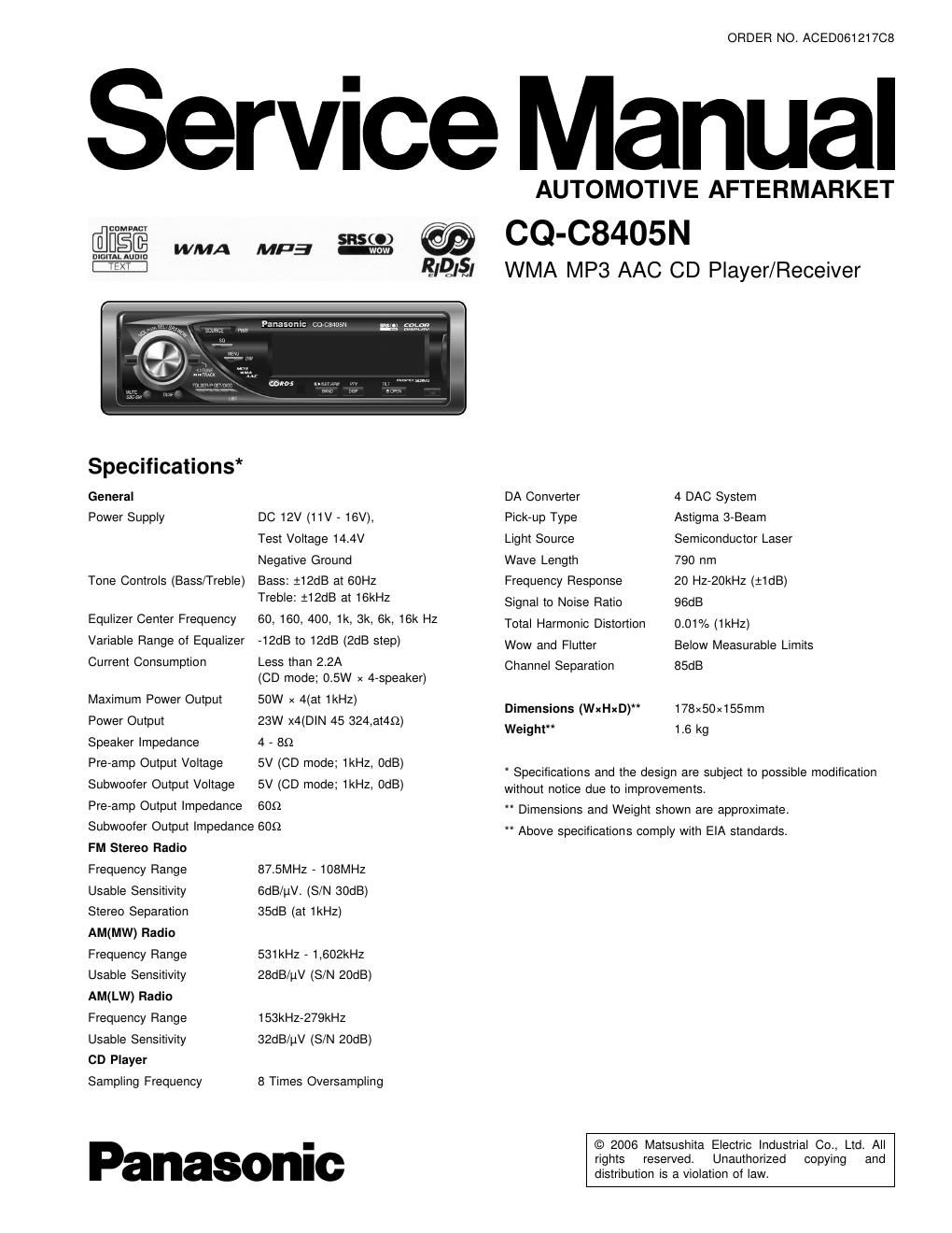
Panasonic cq c 8405 n service manual

This is the 48 pages manual for panasonic cq c 8405 n service manual.
Read or download the pdf for free. If you want to contribute, please mail your pdfs to info@audioservicemanuals.com.

Page: 1 / 48
left right
panasonic cq c 8405 n service manual

Extracted text from panasonic cq c 8405 n service manual (Ocr-read)


Page 2

AWARNING

This service information is designed for experienced repair technicians only and is not designed for use by the general public.

It does not contain warnings or cautions to advise non-technical individuals of potential dangers in attempting to service a product.
Products powered by electricity should be serviced or repaired only by experienced professional technicians Any attempt to service
or repair the product or products dealt with in this service information by anyone else could result in serious injury or death

IMPORTANT SAFETY NOTICE

There are special components used in this equipment which are important for safety. These parts are marked by A in the Schematic
Diagrams, Circuit Board Diagrams, Exploded Views and Replacement Parts List It is essential that these critical parts should be replaced
with manufacturers specified parts to prevent shock, lire or other hazards. Do not modify the original design without permission of

manufacturer.

CONTENTS

Page
1 ABOUT LEAD FREE soLDER (PbF) ....................................... 3
2 FEATUERS ------------------------------------------------------------------------------ 3
3 REPLACEING THE FUSE -------------------------------------------------------- 3
4 MAINTENANCE ----------------------------------------------------------------------- 3
5 NOTES ----- .3
6 DIMENSIONS .3
7 LASER PRODUCTS ................................................................. 3
8 WIRING CONNECTION ............................................................ 4
9 BLOCK DIAGRAM ................................................................... 5

10 DISASSEMBLY INSTRUCTIONS ---------------------------------------------- 9

Page
11 TERMINALs DESCRIPTION --------------------------------------------------- 12
12 I0 BLOCK DIAGRAM ------------------------------------------------------------- 1s
13 REPLACEMENT PARTS LIST ------------------------------------------------ 19
14 EXPLODED VIEW (Unit) -------------------------------------------------------- 26
15 CD PLAYER PARTS LIST ------ -27

16 EXPLODED VIEW (CD PLAYER) -29
17 WIRING DIAGRAM ................................................................. 30
13 SCHEMATIC DIAGRAM --------------------------------------------------- 37
19 SCHEMATIC DIAGRAM for printing with A4 size ----------------- 43