Optonica st 3636 hb service manual

This is the 38 pages manual for optonica st 3636 hb service manual.
Read or download the pdf for free. If you want to contribute, please mail your pdfs to info@audioservicemanuals.com.

Page: 1 / 38
left right
optonica st 3636 hb service manual

Extracted text from optonica st 3636 hb service manual (Ocr-read)


Page 1

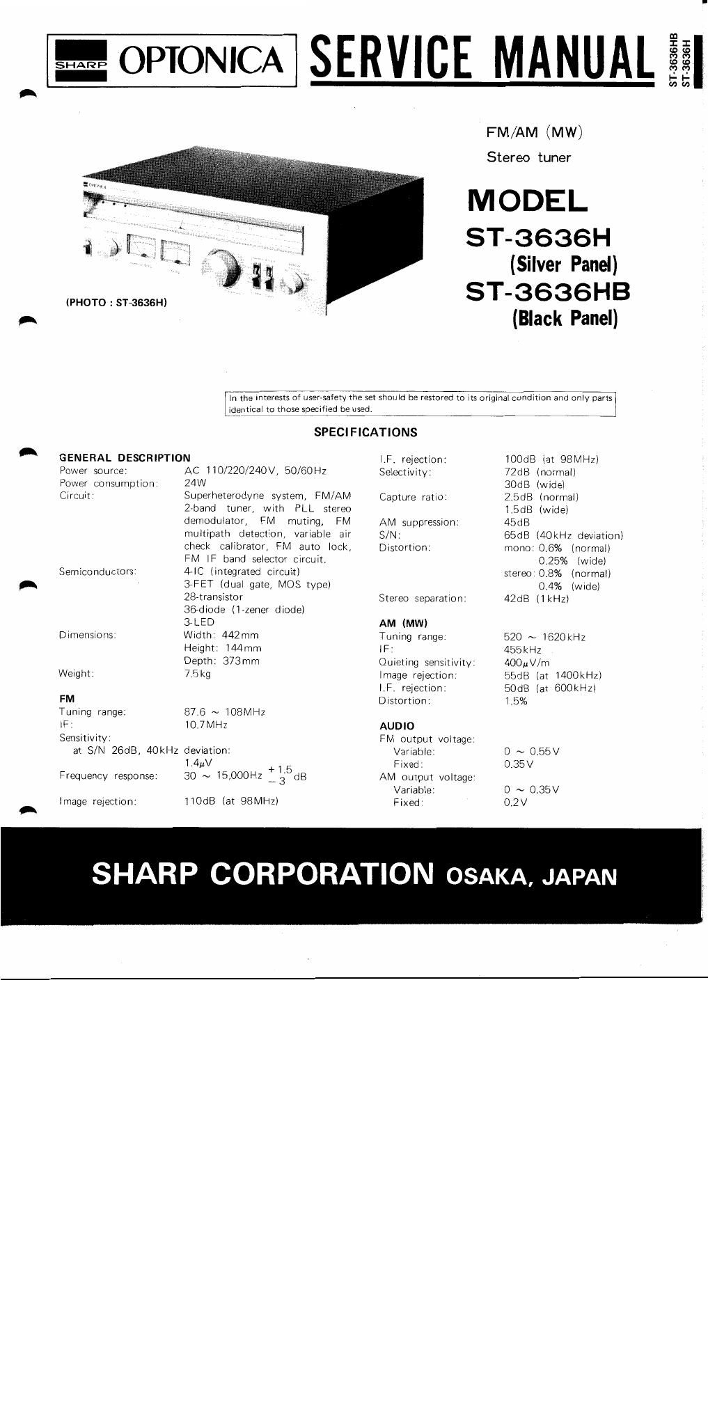
%OPTONICA SERVICE MANUAL

FM/AM (MW)

Stereo tuner

MODEL

ST-3636H
(Silver Panel)

(PHOTO : ST-3636H) ST_3636HB
A (Black Panel)

ST- 3636 H B
ST- 3636 H

Iii-tile interests of usersaiety the set shou Id be restored to its original condition and only partgi
identical to those specified be used. I

SPECIFICATIONS
A GENERAL DESCRIPTION (F. rejection: iOOdB (at 98MHZ)

Power source: AC ll0/220/24OV, 50/60H2 Selectivitv' 72dB (normal)

Power consumption: 24W 30dB (wide)

Circuit: Superheterodyne system, FlVl/AM Capture ratio: 2:5dl3 (normal)
Zrband tuner, with PLL stereo 1.5dB (wide)
demodulator, FM muting, FM AM suppression: 45dB
multipath detection, variable air S/N: 65:38 (40kHz deviation)
check calibrator, FM auto lock, Distortion: mono:0,6% (normal)
FM IF band selector circuit. 0.25% (wide)

Semiconductors: 4-IC (integrated circuit) stere0'0.8% (normal)

A 37FET (dual gate, MOS type) 0.4% (Wide)
28-transistor Stereo separation: 42dB (lkHz)
367diode (lazener diode)
37LED AM (MW)

Dimensions: Width: 442mm Tuning range: 520 ~ iGZOkHz
Height: 144mm IF' 455kHz
Depth: 373mm Quieting sensitivity: 400uV/m

Weight: 7.5kg Image rejection: 55d8 (at l400kHzI

(F. rejection: 50dB (at 600kHzl

FM Distortion: i.5%

Tuning range: 87.6 ~ 108MHz

lF: iO.7I\/IH2 AUDIO

Sensitivity: FM output voltage.

at S/N ZGdB: 40kHz deviation: Variable: 0 ~ 0,55V
1.4uV +1 5 Fixed: 0,35V

Frequency response: 30 ~ l5,000Hz M3; dB AM output voltage:

Variable 0 ~ 0.35V

Image reiection: l10dB (at 98MHZ) Fixed: 02v

SHARP CORPORAT ON OSAKA, JAPAN

Page 2

VOLTAGE SELECTlON

Check the preset voltage before connecting the mains plug
to a mains outlet. If the setting is different from your local
supply mains voltage, the selector must be reset as follows.
Rotate the voltage selector by using a screw driver so that

your local voltage number can be seen.

Prior to removing the chassis, be sure to
draw the power supply plug from a wall
outlet. Then, proceed with the removal
work in the following order after disconnect-
ing all of the connection cords at the rear
of the set.

H To remove the cabinet:

Remove 12 screws ® retaining the

cabinet (6 screws each for the right

and left sides), then the cabinet can
be detached.
2) To remove the bottom board:

Turn over the set and remove 8 screws

(2 retaining the bottom board, then

the bottom board can be detached.

3) To remove the front panel'

ll) Use a hexagonal wrench (1.4mm)
to loosen the screw retaining the
tuning knob (3) at the front panel,
and pull out the tuning knob.

(2) Pull out the remaining knobs @
l5 knobs).

(3) Finally remove 4 screws 6)) retain»
ing the front panel, then the iront
panel can be detached,

L Figure 'l
DISASSEMB LY

Figure 2 DISASSEMB LY