Optonica sm 5200 h service manual

This is the 22 pages manual for optonica sm 5200 h service manual.
Read or download the pdf for free. If you want to contribute, please mail your pdfs to info@audioservicemanuals.com.

Page: 1 / 22
left right
optonica sm 5200 h service manual

Extracted text from optonica sm 5200 h service manual (Ocr-read)


Page 1

= OPTONICA SERVICE MANUAL

( ' ATSM980102PMA

SM-5200H
SM-SZOOHB

STEREO AMPLIFIER

MODEL
SM-5200H

(Silver Panel)

SM-5200HB

(Bronze Panel)

V . . //(V s
Imaggi W4 4
WM /41, W4, mm
Wwfifgg ///Wm/w/, m Ir/4 4%
» 4,, , w W my
WWMéfify f;
W W

3333/)

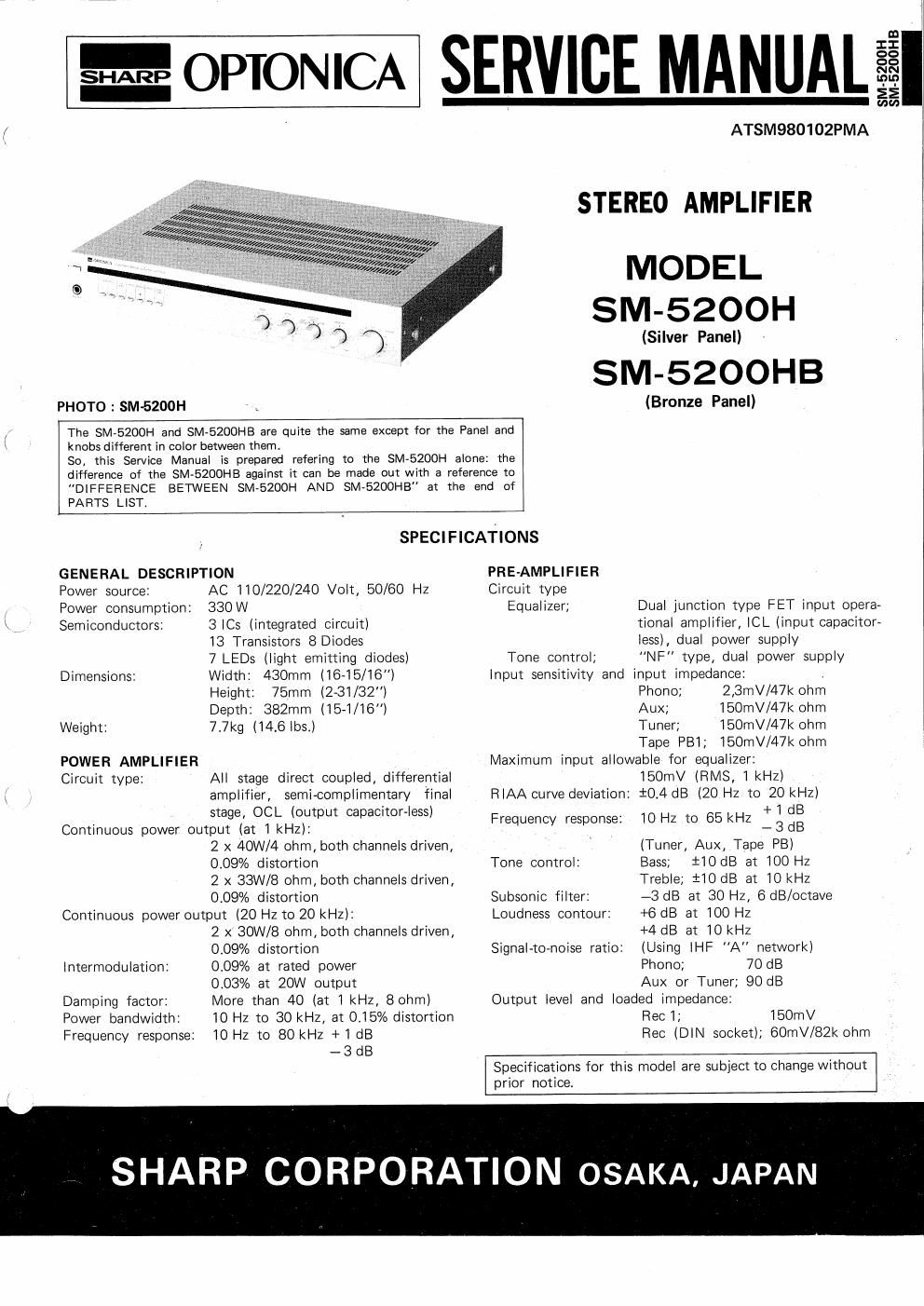
PHOTO : SM-SZOOH

The SM-5200H and SM-SZDOHB are quite the same except for the Panel and
knobs different in color between them,

So, this Service Manual is prepared refering to the SM-SZOOH alone: the
difference of the SM-SZOOHB against it can be made out with a reference to
DIFFERENCE BETWEEN SMvEZODH AND SM-SZOOHB" at the end of

SPECIFICATIONS

GENERAL DESCRIPTION PRE-AMPLIFIER

AC 110/220/240 Volt, 50/60 Hz
330W

3 ICs (integrated circuit)

13 Transistors 8 Diodes

7 LEDs (light emitting diodes)

Power source:
Power consumption:
Semiconductors:

Dimensions: Width: 430mm (16-15/16)
Height: 75mm (2-31/32")
Depth: 382mm (15-1/16)
Weight: 7.7kg (14.6lbs.)

POWER AMPLIFIER
Circuit type: All stage direct coupled, differential
amplifier, semi-complimentary final
stage, OCL (output capacitor-less)
Continuous power output (at 1 kHz):
2 x 4OW/4 ohm, both channels driven,
0.09% distortion
2 x 33W/8 ohm, both channels driven,
0.09% distortion
Continuous power output (20 Hz to 20 kHz):
2 x BOW/8 ohm, both channels driven,
0.09% distortion
0.09% at rated power
0.03% at 20W output
More than 40 (at 1 kHz, Bohm)
10 Hz to 30 kHz, at 0.15% distortion
10Hz to 80kHz +1 dB
- 3 dB

Intermodulation:

Damping factor:
Power bandwidth:
Frequency response:

Circuit type
Equalizer; Dual junction type FET input opera»

tional amplifier, lCL (input capacitor-

Iess), dual power supply

Tone control; NF type, dual power supply

Input sensitivity and input impedance: .

l
PARTS LIST.

Phono; 2,3mV/47K ohm
Aux; 150mV/47k ohm
Tuner; 150mV/47k chm
Tape PBI; i50mV/47K ohm

Maximum input allowable for equalizer:
lBOmV (RMS, 1 kHz)
RIAA curve deviation: iO.4 dB (20 Hz to 20 kHz)
+1 dB
10 Hz to 65kHz -3dB
(Tuner, Aux, Tape PB)
Tone control: Bass; ilOdB at 100 Hz
Treble; iIO dB at 10 I -3 dB at 30 HZ, BdB/octave
+6 dB at 100 Hz
+4 dB at 10 kHz
(Using IHF A network)
Phone; 70 dB
Aux or Tuner; 90 dB
Output level and loaded impedance:
Rec 1; 150mV
Rec (DIN socket); 60mV/82k ohm

Frequency response:

Subsonic filter:
Loudness contour:

Signal-toenoise ratio:

Specifications for this model are subject to change without
prior notice.

SHARP CORPORATION OSAKA, JAPAN

Page 2

FEATURES

DISTORTION-FREE POWER AMPLIFIER

The differential amplifier and direct coupled complementary
OCL circuitry in the amplifier stages provide broad band
power with minimum distortion.

EOUALIZER WITH DUAL POWER SUPPLY

[CL equalizer amplifier includes a dual power supply system
(plus 15\/ and minus 15V) to improve the signal-to»noise
ratio, assuring a greater dynamic range,

NF TYPE TONE CONTROL

Bass and treble controls permit a wide variety of tone control
and allow sound to be adjusted to personal taste and room
acoustics.

TAPE DUBBING -
Tape dubbing from Tape 2 to "Tape 1" is possible, with
the connection of two separate tape decks.

SUBSONIC FILTER
6dB octave filter effectively reduce unwanted noise at low
end of the sound spectrum.

DUAL SPEAKER OUTPUTS

Connections are provided for two separate pairs of speakers
with front mounted control for separate or combined op-
eration.

NAME OF PARTS

CD ® @®@®.

PHOTO: SM-5200H
Figure 2-1

PHOTO: SM-5200H

Figure 2-2

FRONT PARTS
(D Power on/off switch Loudness contour
® Headphones jack Bass contorl
Speakers selector «l Treble control
@ Subsonic filter ® Function selector
© lVlono switch 8 Balance control
© Tape dubbing 2 -> 1 Volume control
® Tape monitor switch

@.®

FRONT PARTS

50592: mini; new
name 145;, mm El

REAR PARTS

@ Earth terminal

@ Phono input sockets

@Tuner input sockets

® Auxiliary/Tape 2 input
sockets

:Tape 1 input sockets

Tape 1 output sockets

@ Tape 1 record/play
back socket

® Speaker A terminals

@ Speaker B terminals

® Mains voltage selector

'2 Fuse holder

\J