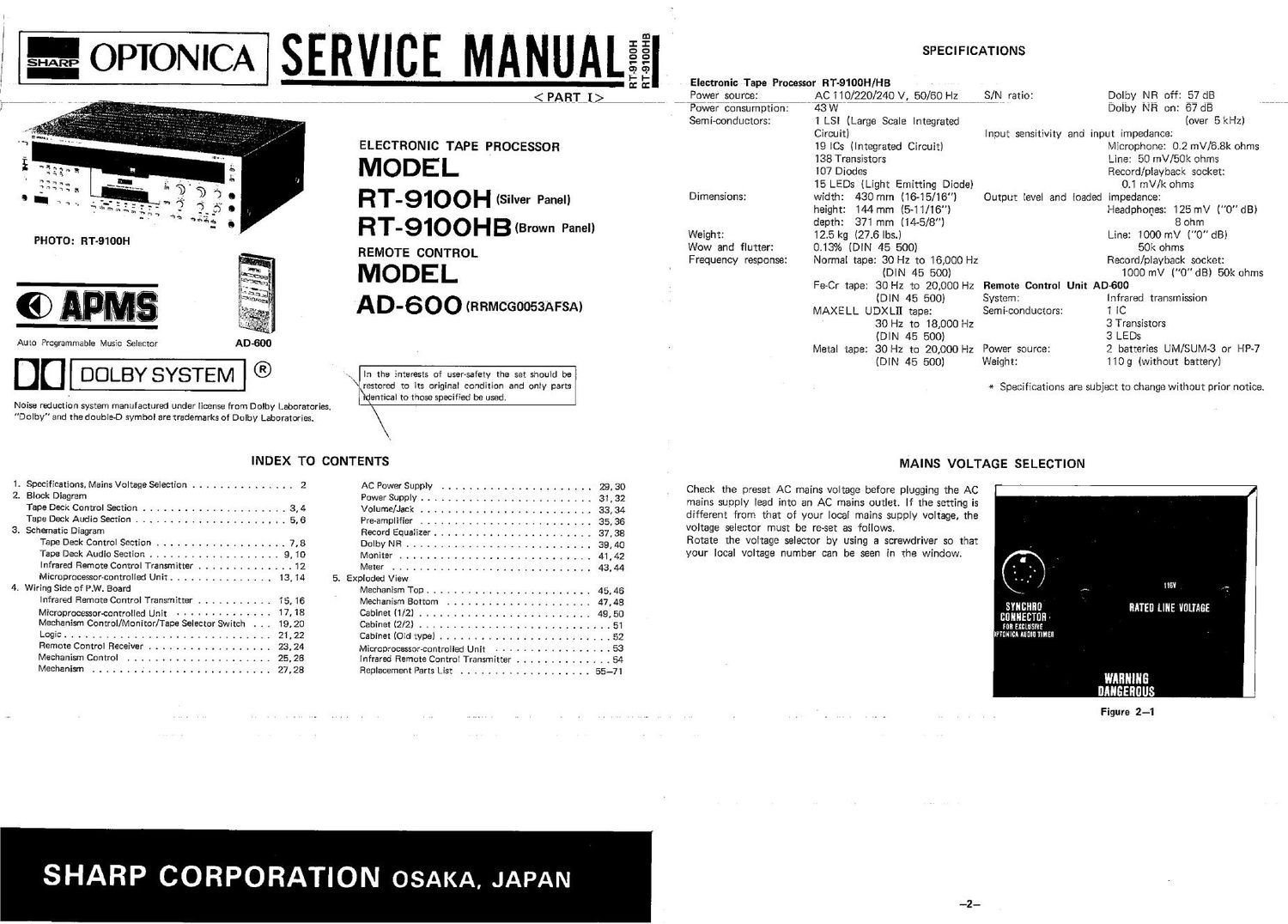
Optonica rt 9100 hb service manual

This is the 47 pages manual for optonica rt 9100 hb service manual.
Read or download the pdf for free. If you want to contribute, please mail your pdfs to info@audioservicemanuals.com.

Page: 1 / 47
left right
optonica rt 9100 hb service manual

Extracted text from optonica rt 9100 hb service manual (Ocr-read)


Page 1

= OPTONICA

PHOTO: RT-9100H

GD APMS

Auto Programmable Music Selector

DC] DOLBY SYSTEM

SERVICE MANUAL

< PABIJ}

RT-9100H

ELECTRONIC TAPE PROCESSOR

MODEL

RT-91OOH (Silver Panel)
RT-91OOHB(Brown Panel)

REMOTE CONTROL

MODEL
AID-600 (RRMCGoossAFSA)

In the interests of user-safety the set should be
\ restored to its original condition and only parts
\dentical to those specified be used:

Noise reduction system manufactured under license from Dolby Laboratories.
Dolby and the double-D symbol are trademarks of Dolby Laboratories.

INDEX TO CONTENTS

1. Specifications, Mains Voltage Selection ............... 2 AC Power Supply ...................... 29, 30

2, Block Diagram Power Supply ......................... 31 . 32

Tape Deck Control Section ..................... 3, 4 Volume/Jack ......................... 33, 34

Tape Deck Audio Section ...................... 5, 6 Pre-amplifier ......................... 35, 36

3. Schematic Diagram Record Equalizer ....................... 37, SB

Tape Deck Control Section ................... 7, 8 Dolby NR ........................... 39, 40

Tape Deck Audio Section ................... 9, 10 Moniter ............................ 41,42

Infrared Remote Control Transmitter .............. 12 Meter ............................. 43, 44
Microprocessor-controlled Unit ............... 13, 14 5. Exploded View

4. Wiring Side of P.W. Board Mechanism Top ........................ 45, 46

Infrared Remote Control Transmitter ........... 15,16 Mechanism Bottom ..................... 47,48

Microprocessor-controlled Unit .............. 17, 18 Cabinet (1/2) ......................... 49, 50

Mechanism Control/Monitor/Tape Selector Switch 19, 20 Cabinet (2/2) ............................ 51

Logic .............................. 21 , 22 Cabinet (Old type) ......................... 52

Remote Control Receiver .................. 23,24 Microprocessor-controlled Unit ................. 53

Mechanism Control ..................... 25, 26 Infrared Remote Control Transmitter .............. 54

Mechanism .......................... 27, 28 Replacement Parts List ................... 55-71

SHARP CORPORATION OSAKA, JAPAN

RT-91OOHB

SPECIFICATIONS

Electronic Tape Processor RT-9100H/HB
Power source: AC 110/220/240 V, 50/60 Hz
Power consumption: 43W
Semi-conductors: 1 LSI (Large Scale Integrated
Circuit)
19le (Integrated Circuit)
138 Transistors
107 Diodes
15 LEDs (Light Emitting Diode)

S/NW ratio:

Dimensions: width: 430 mm (16-15/16")
height: 144 mm (5~11/16")
depth: 371mm (14-5/8)
Weight: 12.5 kg (27.6 lbs.)

013% (DIN 45 500)
Normal tape: 30 Hz to 16,000 Hz
(DIN 45 500)

Wow and flutter:
Frequency response:

Dolby NR off: 57 dB

Dolby NR on: 67 CIR WWW
(over 5 kHz)

Input sensitivity and input impedance:

Microphone: 0.2 mV/68k ohms
Line: 50 mV/50k ohms
Record/playback socket:

0.1 mV/k ohms

Output level and loaded impedance:

Headphones: 125 mV ("0" dB)
8 ohm
Line: 1000 mV (0"dB)
50k ohms
Record/playback socket:
1000 mV l0dB) 50k ohms

Fe-Cr tape: 30 Hz to 20,000 Hz Remote Control Unit AD~600

System:
Sem i-conductors:

(DIN 45 500)
MAXELL UDXLH tape:
30 H2 to 18,000 Hz

(DIN 45 500)
Metal tape: 30 Hz to 20,000 Hz Power source:
(DIN 45 500) Weight:

Infrared transmission

1 IC

3 Transistors

3 LEDs

2 batteries UM/SUM-3 or HP~7
1109 (without battery)

* Specifications are subject to change without prior notice.

MAINS VOLTAGE SELECTION

Check the preset AC mains voltage before plugging the AC
mains supply lead into an AC mains outlet. If the setting is
different from that of your local mains supply voltage, the
voltage selector must be reset as follows.

Rotate the voltage selector by using a screwdriver so that
your local voltage number can be seen in the window.

All I

I :lIIHIII
Figure 2-1

_2_

Page 2

MECHANISM CONTROL SWITCH
APSS

cum
soup Iov fwd law may n In: pause spaclng
swaa swzs SW26 SW27 SW28 SWZS swsc swaI SW32


' SWITCHING l J; l l l l l l l
CONTROL UNIT (LI30I7,LCD] 1 1 1 1 1 1 1 1 1 INFRARED REMOTE
026 > 009 o T T T T T T T T I CONTROL REMOTE osc
CONTROL -_
PLI PI2 PL4 QIOIO I REGEWER IN RESONATOR
- |7V K4 <2 Ololl 1:1 FIGOI
MECHANISM CONTROL | _ _ osc 455KHZ
CIRCUIT EILATERAL BCD DECIMAL DECORDER OUT
_ 5V SWITCH I
4m:
LCD ICIOOI ICIooa <2 PO~3 ,
02l~25 .Clooz <: ' " ICIOO4
044446
SWITHING
- QIOOG
SI ov @- OIOOB
IR AC A
-N-" NOISE
Dlooa REDUCTION
Fl! 4 INFRARED 01004 OIooz
{} | RECEIVING 01005 Oloos
INDICATOR I
050 32.761011 RESET A
- <- 3v -.5v PRE AMP.
04 , Q3: 02, 0 INTERFACE
a <- OIOOI
-|(§ IOI2
P <- DIOOO lc|005
Photo Diode
fi R2 ms 023 033 045 RI °'°' 38
53n- ZLWE APMS RLveos
INSTRUCTION DECORDER REEL SOLENOID CONTROL REEL
SWITCHING TO 3v LEVEL Fl SOLENOID
'NTERFACE DA R-SOL Q4OI~0406 Bflsomoz
I' 0 '0 -FI2> m3 C-SOL
... _ - <1- I
1: RD" -I>F3 CLKI R - M2 cAPSrAN SOLENOID CONTROL
03 O7 06 05 F4 _ CAPSTAN
D CLKZ R M' O407~O412 BHSOLENOID
I , |/5REW SOL4OI
SW22 swm SWI9 ssz c M
Timer Erase Cassette Pwer _
5"de Protection Loading State 015 020 HALL INVERTER REEL MOTOR CONTROL
I "' Ic ICI . Icz (Rewind)
sw2o IO4OI 0430
Cassene AUTO CLEAR REC BIAS REVERSING CIRCUIT
Nd" COUNTER PULSE _ REEL MOTOR
GENERATOR an ACL REC MUT R MOTOR CONTROL O426~O429 M2
ICI004,ICI005 TIMER SYNCHRONOUS BEEP 5b PLAY MUT 55"
+I2v @->{QIOOI~QIOOS OPERATION osc (Fast-forward)
OIOIz -> O425
v TIMECOUNTER
IOIOOI~ICI003 m2 QI3~QI5 DU J) START/STOP
" 5V ®->{ Ql3~015.016 -" _ auto REEL MOTOR GOVERNOR
V LEO (D|6~D23) Plezo QIT CONTROL UNIT A Buzz D23 _> 0419 _.> Q42|~Q424
+3V @-> 05~08 +. pause 0420
QIOOS~QIOII 2 D22
+- '9 SWITCHING
+av ®-> QIO,QIB~'020 5 92' 3335;):
. o o SW23 +. ff D Q43| D m ssm CAPSATNMOTOR
BEEP Tone } 0432 c-MOTOR M I
0 ° 92° ASSEMBLY
+5V ®-> ICI,Ic2,OI D4,QS,QII,QIT 7K-- play
(Back II ) DI9
p TIMER SOCKET > few >®Blus un/fo
+I2V ®_> [C40] DC Back up from AUDIO TIMER © 09 ,5 DIS >®Rec MuIlng
(ADZOOT) APMS signal _K__.. fwd-APSS
AUTO CLEAR ,5 D PLAV MUTING
+ IEV ®-. +- rev-APSS .
MECHANISM 2 me ________> 0'5 D (9 Mm
CONTROL CIRCUIT + 5v :
+ I2 v @->